5-axis machining for inclined surfaces
The high-performance 5-axis CNC milling machining center, the CNC system has the space coordinate system rotation and the inclined tool compensation function, which provides the possibility for the machining of some parts that require inclined surface machining and high machining accuracy. When machining on an inclined plane, it is difficult to compile a machining program because the coordinate system changes in space. Need to break through the conventional programming thinking mode for programming, and special processing of the program. This article discusses this issue in conjunction with the actual processing of model products.
Such parts are often encountered in the production process of products, and they need to be punched, bored, and milled on the inclined surface. Or it needs to be processed on several inclined surfaces with different directions and different slopes in the same clamping, and each inclined surface has a higher geometric tolerance requirement. The conventional method of processing such parts is to pull the head of the bed, rotate the work surface or use a modular fixture. If the processing direction or processing position is different, a second clamping and re-alignment are required, and the processing process is extremely cumbersome. Due to the limitation of the clamping positioning and the machine tool itself, the machining accuracy of the parts cannot be guaranteed. For example, in the T×× table body processing, there are many holes on the inclined surface, and the special-shaped surface is not easy to clamp, the positioning reference is not good, and the error accumulation caused by multiple clamping, sometimes the hole margin error exceeds 1mm.
In order to solve the processing problem of this kind of parts, through continuous exploration and continuous improvement of process methods, combined with the factory's existing machine tools, a five-axis CNC milling machining center was selected to solve this problem. The selected machine tool is 5-axis linkage. In addition to 3 linear axes, it also has two rotary axes (C axis: -360°~360°) and swing head (B axis: 0°~110°). The control system used is FANUC160i, which has the functions of space coordinate system rotation and inclined tool compensation.
From the perspective of realizing bevel processing, multiple bevels in different directions and different angles can be punched, boring, tapped, milled and other processes can be completed after one clamping. Reduce the number of clamping times, reduce labor intensity, shorten the production cycle of the product, and more importantly, improve the processing accuracy of the parts and ensure the consistency of product quality.
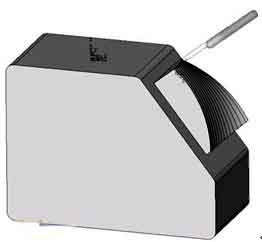
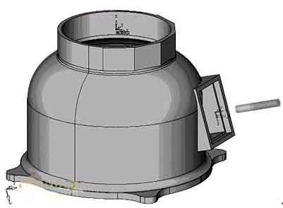
Take the processing of a certain base part as an example. The parts are shown below: To process this base, it can be seen that the machine tool should complete a 2-axis linkage interpolation on the XZ and YZ planes and a spindle head swing motion. Because to make the tool perpendicular to the machined surface, the spindle must complete a head swing movement. Having a rotating head involves a series of multi-axis machining issues such as pendulum length. Therefore, it is necessary to use multi-axis programming means to complete. Programming and machine tool debugging are difficult, which puts higher demands on programmers and machine operators. In practical applications, taking into account factors such as ensuring the safety of the machine tool, it is necessary to simulate the processing process and perform multiple air cuts to ensure that the program is correct before formal processing can be performed. In addition, the multi-axis program algorithm is quite complicated, and the influence of factors such as pendulum length needs to be considered. There must be a specific post-processing for a certain machine tool, but the post-processing is often due to the difference in algorithms and control positions, as well as the influence of calculation stability. The program obtained through software post-processing is often difficult to meet the requirements of the accuracy of part drawings in terms of control accuracy.
The analysis shows that the direct cause of the increase in programming difficulty is the appearance of the inclined plane. Therefore, if the machining plane can be made to coincide with the inclined plane, then this kind of problem will be transformed into a two-axis semi-processing programming problem, and the programming difficulty will be greatly reduced. Therefore, it is conceivable to use the coordinate system conversion function of the machine tool (G68 command) to make the machining plane coincide with the inclined plane. The second tool length compensation command (G432) is used to add the tool length in the vertical direction of the inclined plane. After the above processing, the problem of bevel processing is transformed into plane processing to solve, thus the programming difficulty is greatly reduced. If you need to process multiple inclined planes at the same time, you only need to rotate the C axis to C0 (the zero position of the worktable, the direction of the zero position is the same as the swing direction of the spindle), and then realize the processing by rotating the coordinate system and increasing the tool length. If the processing shape is relatively simple, programming can be done manually. This makes it possible to realize the machining of multiple inclined surfaces, multiple positions, and multiple tool changes in a single clamping of the CNC machine tool.
The program structure is as follows:
%
N0100O0008 (program name)
N0102M6T1; (tool change)
N0104G0G90G56X400Y200Z260B0C0; (Move to the reference point)
N0106G432X200Z150H1Bω; (add the knife length in the direction perpendicular to the inclined plane)
N0108M3S3000; (Spindle forward rotation)
N0110M8; (open cutting fluid)
N0112G68X188Y0Z60I0J1K0Rω; (Coordinate system conversion, ω is the angle of rotation of the main shaft from zero to perpendicular to the inclined plane)
……
N0200G69; (cancel coordinate system rotation)
N0202G492X200Z300; (Slope tool compensation canceled, move to a safe position)
N0204M9; (cutting fluid off)
N0206Cα; (C axis rotation, α is the minimum angle between the vertical line of the nth inclined plane to be processed and the C0 position)
N0208G0G90G56X400Y200Z260B0C0; (Move to the reference point)
N0210G432X200Z150H1Bωn; (add the knife length in the direction perpendicular to the inclined plane)
N0212G68X188Y0Z60I0J1K0Rωn; (Coordinate system conversion, ωn is the angle of rotation when the main shaft turns from zero to perpendicular to the slope)
...
N0200G69; (cancel coordinate system rotation)
N0202G492X200Z300; (Slope tool compensation canceled, move to a safe position)
N0204M9; (cutting fluid off)
N0204M30; (program ends, return to program head)
Although the bevel machining has been achieved in the above discussion, it is limited to drilling, boring, tapping, and milling on the bevel. The simple shapes composed of straight lines and arcs are limited to manual programming. If the milling shape is more complicated. Such as milling equation curves, three-dimensional curved surfaces, and lettering on an inclined plane, how to program it?
Even when these similar shapes are processed on a flat surface, manual programming is not possible, and it can only be completed by CAM software. Through careful study of machine tools and CAM software, a set of software programming combined with manual programming was found to be an effective way to complete the processing and programming of such parts.
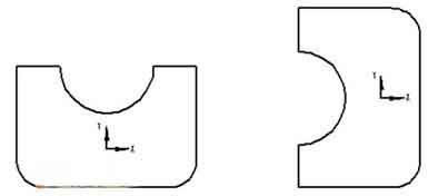
The analysis shows that in ordinary three-axis milling programming, the direction of the tool axis is always perpendicular to the XOY plane. But when the spindle deviates from the original vertical direction and the tool plane is inclined, how can the program generated on the XOY plane run correctly on the inclined plane? The analysis shows that although the coordinate system has been rotated, if the relative position of the figure (a) in the original coordinate system and the shape to be processed on the inclined plane (b) and the relative position in the new coordinate system are kept consistent on the XOY plane . Then the program generated on the XOY plane can be directly applied to bevel machining.
According to the influence of the swing head movement of the machine tool on the graphics position, the analysis shows that when drawing on the XOY plane, the graphics should be rotated 90° counterclockwise with the programming origin as the rotation center (the rotation angle should be determined according to the specific conditions of the machine tool). In this way, the graphic position in the CAM software is kept consistent with the actual machining position. By adding and modifying the program head and program end, that is, adding coordinate system conversion and inclined tool compensation, software programming and manual programming are combined. This realizes the machining of arbitrary complex shapes such as milling equation curves, three-dimensional curved surfaces, and lettering on the inclined surface.
Through the actual machining verification, it is confirmed that the method is within the allowable range of the machine function and stroke, and the programming of this method can realize the machining programming of any complicated shape on any inclined plane.
The following figure shows an example of processing a three-dimensional curved surface on a 52° inclined plane: