Functions and Applications of 5-axis CNC Milling
What can be done with a 5-axis milling machine?
It may sound strange, but if the Renaissance artist had traded the hammer and chisel for a numerical control (CNC) and milling machine, we would have thousands of statues of David made from all kinds of materials today.If you still have doubts that 5-axis milling is a real art form, please click here or here.
Whether you are sculpting a masterpiece out of marble or milling a blisk out of titanium - the basic principle is the same: You start off with a block of the material and remove the excess pieces until only the target object remains. Of course, the details of this process are much more complicated, especially with 5-axis milling.
What is 5-axis CNC milling?
Put simply, with 5-axis milling, an object or the milling tool is moved simultaneously along five different axes by means of a CNC control. This enables very complex parts to be machined, which is why 5-axis technology has proven itself particularly in the aerospace industry.However, this is not the only reason that 5-axis technology has become widespread. Other factors are:
1 , A trend towards single-setup object processing (sometimes referred to as “done-in-one”) to reduce turnaround time and improve efficiency
2 , The possibility of preventing accidents at work by tilting the milling element or the milling table in a controlled manner, which also enables the process to be better coordinated with the geometry of the respective object
3 , The optimization of the tool life and the tool cycle as a side effect of the above-mentioned tilting function of the milling element or milling table by ensuring an optimal cutting position and a constant metal removal rate
What about the axes in the 5-axis machining process?
We all know the story of Newton and the apple, but there is a story of the mathematician and philosopher René Descartes of similarly dubious origins.Descartes was in bed (as mathematicians and philosophers do) when he noticed a fly buzzing through his room. He realized that he could describe the position of the fly in the three-dimensional space of the room with only three numbers, represented by the variables X, Y and Z.
This is the Cartesian coordinate system that is still in use today, more than three centuries after Descartes' death. X, Y and Z therefore cover three of the five axes of the 5-axis machining process.
But what about the other two axes?
Imagine zooming in on Descartes ’fly in mid-flight. Instead of just describing their position as a point in three-dimensional space, we can also describe their orientation. When the fly changes direction, it does so in the same way as an airplane that tilts to maneuver. The fourth axis, A, describes its lateral rotation around its own axis as an axis of rotation around X (called “rolling” in technical terms).Following on from the aircraft comparison, the vertical inclination of the fly upwards or downwards is described by the fifth axis, B, as the axis of rotation around Y (called “nodding” in technical terms).
The careful reader will no doubt infer the existence of a sixth axis, C, rotating around the Z axis. In our example this is the horizontal rotation of the fly to the left or right (called “yaw” in technical terms).
If you have difficulty visualizing the six axes described above, the diagram below should serve as a guide:
The axes A, B and C are arranged alphabetically to match the axes X, Y and Z accordingly. Although there are 6-axis CNC machines such as For example, the portal milling machine Zimmermann FZ 100, 5-axis configurations are more common, as the sixth axis usually offers hardly any additional use.
A final note on the conventions of axis designations: In a vertical machining center, the X and Y axes correspond to the horizontal plane, while the Z axis corresponds to the vertical plane. In a horizontal machining center, the Z and Y axes are swapped. See the diagram below:
5-axis configurations
The specific configuration of a 5-axis milling machine determines which of the three axes of rotation it uses.So z. B. a swivel table machine with the A-axis (rotating around the X-axis) and the C-axis (rotating around the Z-axis), while a swivel head machine with a B-axis (rotating around the Y-axis) and a C -Axis (rotating around the Z-axis) is working.
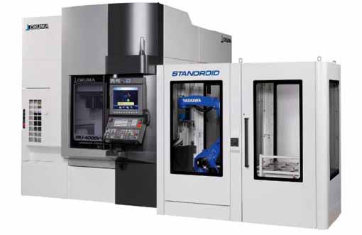
Inside view of the swivel table of the 5-axis, vertical machining center of the Okuma MU-4000V
The axes of rotation in swivel table machines are operated by the movement of the table, while swivel head machines operate their axes of rotation by rotating a spindle. Both types have their own advantages. For example, swivel table machines offer larger processing chambers because the swivel spindle does not require significant space. On the other hand, swivel head machines can also process heavier parts because the table is always horizontal.
How many axes are required?
You may have heard of machining centers with seven, nine, or even eleven axes. Although so many additional axes seem hard to imagine, the explanation for such staggering numbers is actually quite simple.“When you are dealing with machines that e.g. For example, having more than one turning spindle increases the number of axes, ”explained Mike Finn, Senior Engineer Industrial Applications at Mazak America.
“For example, we have machines with an additional, second spindle and lower turrets. With these machines you have several axes: the upper turret has 4 axes and the lower turret has 2 axes, then you have two opposing spindles that also have 2 axes. Such machines can have up to 9 axes, ”continued Finn.
"The parts you make are still 5-axis parts," added Wade Anderson, product specialist and sales manager at Okuma America.
"A component such. B. a valve for the aerospace industry could easily be manufactured in our vertical machining center MU-5000, a 5-axis machine. We could also machine this part on a multi-axis machine with a B rotation axis and two spindles for two C axes each, plus the standard X, Y and Z axes. There is also the lower turret, which provides you with a second X and Z axis. So there are more machining axes available, but the part itself will have the same geometry, ”said Anderson.
So how many axes are really needed?
As is so often the case in manufacturing, the answer to this question depends on the particular application. Finn gave the following example:“A turbine blade is a free-form surface and can be very complex. The most efficient method of machining such an object is 5-axis machining, in which the tool is guided in a spiral around the profile of the turbine blade. 3-axis machining is possible by fixing the blade in a certain position and then machining the surface along three linear axes, but this is usually not the most efficient method. "
Anderson agreed: "It depends on the geometry of the respective component whether you need a 3, 4 or 5-axis configuration."
However, it is important to note that the number of axes required depends on aspects that extend beyond the object to be processed directly. The target is the main factor, but it's also about the long-term needs and goals of each customer, ”said Anderson.
“A customer could show me a part, such as a titanium bracket for aerospace technology, and I could say, 'This is a perfect part for a 5-axis machining center,' but the customer may already be planning to make parts in the future that can be processed better with one of our MULTUS U machines. This multi-function machine may not be as optimally suited as a 5-axis machining center with regard to the current component, but it offers the customer the possibility of turning, shaft or chucker work that can also be applied to future components. "
“Another aspect to consider is the dimensions of the processing chamber,” added Finn. “What are the maximum dimensions of an object that you can insert into the machine without affecting tool and position changes? It's about understanding what is possible with the system and what is not. "
What are the advantages of 5-axis machining?
Choosing between 3-axis machining and 5-axis machining is a bit like deciding between a MacDonald’s quarter pounder and a T-bone steak; If cost is your only concern, then the first option is clearly a better option.However, if you compare 5-axis machining with 3 + 2-axis machining, the decision is much more difficult.
5-axis vs 3 + 2-axis
In order to understand the subject, it is important to understand the difference between 5-axis machining and 3 + 2-axis machining. The former - also called continuous or simultaneous 5-axis machining, is accompanied by continuous adjustments to the alignment of the cutting tool along all five axes in order to keep the cutting nozzle optimally perpendicular to the workpiece.Demo component made of 6010 aluminum produced on all 5 axes using a DMG MORI DMU50. Processing time: 13 minutes.
With the latter, on the other hand - also called 5-sided or 3 + 2-axis machining - a 3-axis program is executed in which the milling tool is fixed at an angle determined by the two axes of rotation. If the tool is realigned along the rotational axes between cuts, the process is called "5-axis indexed"; however, it is still one of the 3 + 2-axis machining processes.
3 + 2-axis demo component made of 6010 aluminum, produced on a DMG MORI DMU50. Processing time: 7 minutes.
The main advantage of 5-axis continuous machining over 5-axis indexed machining is speed, as the latter has to be stopped every time the tool is realigned, while the former does not.
In principle, however, it is possible to achieve the same results with both variants. (Readers who disagree are welcome to share their examples of parts that can only be machined with continuous 5-axis technology in the comments section below the article.)
It should also be mentioned that the speed advantage is bought at the price of increased tool activity, which is associated with increased wear and tear and an increased need for crash detection. This is one of the reasons why continuous 5-axis machining is more of a challenge from an operational point of view.
5-axis machining vs. 3D printing
3D printing or additive or generative manufacturing - is currently a hot topic in the production world, especially with regard to the comparison with subtractive manufacturing processes such as 5-axis machining.Although it is sometimes suggested that these two methods are in competition with each other - especially by hardcore 3D fans who claim that the 3D - Technology will soon turn the entire manufacturing industry upside down -, From a more moderate point of view, additive and subtractive manufacturing processes appear rather than mutually complementary technologies.
"I don't think additive manufacturing will completely take over the manufacturing landscape, but I think it offers opportunities to make parts that couldn't have been made in the past," said Finn. “There are still many parts that require subtractive machining. For example parts that have a very low roundness tolerance. "
“It is possible to bring an element to a near net shape without any problems, but this element still has to be reworked in order to achieve sufficient tolerance,” added Finn.
Does that mean that the future of manufacturing lies in a hybrid production system consisting of 3D printing and 5-axis CNC - perhaps with a built-in coordinate measuring machine to check the dimensions?
Anderson was not sure: “The real application of 3D printing outside of a laboratory environment is not to have a combined system, but for example an LMD system (Laser Metal Deposition; German: laser metal deposition) and simultaneously a rotary or Milling machines that both do what they do best and combine both units with automation. "
The point behind two separate systems is better powder and chip management.
"The amount of powder you need on an LMD facility to make a 30-pound part can be anywhere from 150-300 pounds of titanium," said Anderson. "When that is put into a machine that combines all of the functions, it is next to impossible to recover and reuse the powder."
In other words: 3D printing and 5-axis machining are less in competition with one another than they are complementary to one another. “I think that additive manufacturing can immensely reduce the amount of roughing involved in manufacturing,” concludes Finn.
How to get the most out of 5-axis machining
It is not uncommon for the advantages of 5-axis technology to not be used to a sufficient extent.Anderson agreed: "That breaks the heart of companies like ours: When we see a company that goes all-in when purchasing their system and then uses only a fraction of the functions during commissioning for various reasons, e.g. uses a multifunctional system with five or more axes such as a 3-axis system. Something like that happens again and again. "
“Often times this phenomenon is related to the company's HR policy,” added Anderson. “It's about training and understanding how to use a system. Sometimes it is difficult for those responsible to imagine how standard applications can be varied. E.g. whether the respective part could not also be machined with an upper rotation, a lower rotation, a main spindle and a counter spindle at the same time in an integrated process. The possibilities may seem overwhelming to some and overwhelm them. "
The importance of 5-axis control and software
Although having an industrial mechanic with the appropriate qualifications makes a significant contribution to utilizing the full potential of a 5-axis system, the system's control system and software are just as important."With high-speed 5-axis machining, the servo drives on the system and the response time are very important in order to avoid erratic and inaccurate cuts during machining," said Finn. “The system's control system must be able to process the data quickly enough so that the tool can be guided over the object in a nice, smooth movement. You don't want any jerky movements that can lead to deviations and irregularities. "
“The software that creates the 5-axis programs must also be able to generate nice, smooth code so that the system can convert it into a smooth movement,” says Finn.
Choosing the right CAD / CAM package is therefore crucial in order to get the most out of your machine.
"For example, when you're doing aerospace blisks, you have to work with high-end programs," said Anderson. "If, on the other hand, you manufacture small aluminum elements in a die-cast mold for an automotive company and only need to drill a few holes in an engine housing to assemble them, that is of course something completely different."
"If you are cutting parts that a CAM system needs to create specific cutting programs for, you should invest in a CAM system that is tailored to the capabilities of your facility," added Finn.

Avoidance of collisions in 5-axis systems
When creating 5-axis milling paths, there is usually a dilemma between higher cutting and feed speeds and minimizing the risk of accidents and falls. Fortunately, there are a number of software tools out there that can help neutralize these risks."With our collision avoidance software, you can upload a 3D model of the part and tools and the program will check for any risk of collision before the tool moves," said Anderson. "If your device is modeled correctly, the collision will be prevented before the movement begins."
“There is software on the market that can do machine simulations,” commented Finn. “This is extremely important, especially when it comes to more expensive parts. You don't want collisions that would result in you having to scrap a part, injure someone or damage the machine. "
"Vericut offers 3D virtual surveillance software that does the same thing but on an offline computer," added Anderson. "So instead of running on the control system in real time, upload your part data to Vericut and it will examine all of your toolpaths and make sure the system will do exactly what you expect it to."
Tool sensors in 5-axis systems
High productivity is an advantage of 5-axis machining. but it also increases the risk of errors, such as B. Using a damaged tool or the wrong tool. One way to minimize such errors is to use a tool sensor such as B. this BLUM laser on the DMG MORI DMU 50:5-axis technology: everything in just one pass?
The term “Done in One” is a noble ideal in production: You load a block of material into a machine, run the program and receive a completely finished part. Like zero set-up time, Done-in-One is also a worthwhile goal, even if it ultimately cannot be achieved without compromising.Regardless of this fact, 5-axis machining brings us much closer to the goal than any other process, because even 3D printed parts require post-processing. In this context, the clamping technology represents a major limitation with regard to 5-axis machining.
"The clamping technology is immensely important in 5-axis machining," says Anderson. "I can have the best system in the world, but if my clamping technology is lousy, I'll never get the part out that I want at the end of the day."
According to Finn, the key to overcoming this hurdle lies in the use of machines with more than five axes:
"Our INTEGREX machine z. B. can be equipped with counter spindles and a lower milling turret. This allows the parts to be cut on a spindle and then transferred to the sub-spindle to machine the rest of the part. This basically allows you to load a block of raw material and unload a finished part at the end. "
The real art of 5-axis milling
5-axis machining offers significant advantages such as shorter throughput times, higher efficiency and longer tool life. However, it is important to understand that these benefits cannot be realized by just purchasing the latest 5-axis machining center.Mastering the art of 5-axis machining requires considering a variety of factors. On the subject, Anderson said the following:
“If you look at the customer's problems, then technical problems in the course of processing are rather rare. Most of the time, the problems they are faced with revolve around things unrelated to the technology of manufacture, but rather training issues and personnel issues. therefore translate the work plan into adequate system control commands or ensure before processing that enough tools are available to complete the part that has started. The peripheral parts of the process often present a greater challenge than the technical issues involved in manufacturing itself. "
PREV:5-axis Milling of Free-Form Surfaces
NEXT:NONE
NEXT:NONE


