Tool interference prevention for 5-axis milling
With the increase in the design of multi-faceted and complex curved parts, 5-axis machining will account for an increasing proportion of CNC machining. Because 5-axis CNC machining adds two degrees of freedom of rotation, it increases the difficulty of CNC machining motion simulation calculation and tool interference checking, especially when machining parts with extremely complex shapes. Therefore, in order to ensure that 5-axis CNC machine tools perform high-efficiency and high-quality milling processing, the design of 5-axis machining tool path generation and interference checking software will become a major issue.
The feature projection method is suitable for 5-axis CNC machining tool interference processing, that is, the machining surface is discretized into a series of surface feature points. Whether the tool interference occurs can be judged by whether the feature point enters the inside of the tool surface. At the same time, the machining surface and the tool surface are projected onto a specific plane, and only the feature detection points in the curved surface area of the enveloping tool projection graph are checked for interference, which improves the efficiency of interference detection.
1. Inspection method for tool interference
Coordinate system and coordinate transformation
As shown in Figure 1, the local coordinate system L of 5-axis circular cutter milling is represented as XL axis, YL axis and ZL axis. The YL axis always points to the cutting direction f of the tool contact (referred to as CC point) OL. The ZL axis points to the normal direction n of the surface, and the XL axis is determined by the right-hand rule of the YL axis and the ZL axis. The tool generally rotates around the XL axis from the ZL axis to the YL axis by a lead angle (heel angle) a, and rotates around the ZL axis one by one side slip angle b. In addition, the tool coordinate system T (XT, YT, ZT) can also be defined at the tool location point (CL point for short) OT. The YT axis points to the direction of the line connecting the CL point and the CC point. The ZT axis is the tool axis vector direction, and the XT axis is the direction determined by the right-hand rule of the YT axis and the ZT axis. The coordinate origin is located at the tool center point (ie CL point) OT. In order to simplify the interference check, the tool surface with a relatively regular shape is used as the reference for interference check. The machined surface is discretized to express the shape of the surface in the form of a set of characteristic points. The original data of these feature points are expressed in the world coordinate system W, so the feature point data must first be transformed from the world coordinate system W (OW-XW, YW, ZW) to the local coordinate system L (OL-XL, YL, ZL) ). It is then transformed from the local coordinate system L to the tool coordinate system T (OT-XT, YT, ZT).
Interference check method
If the tool and power head have been selected, the size of the tool system (tool and power head) is known. Whether the tool system interferes with the machined surface can be determined by judging whether the characteristic point P enters the inside of the tool surface. As shown in Figure 2, it is the positional relationship between the tool system and the machined surface when the ring knife is processed. In the tool coordinate system, let the coordinate of the characteristic point P be PI (Xpt, Ypt, Zpt). According to the different combination parts of the tool system, the coordinate value Zpt of the characteristic point P is divided into 4 sections for judgment. Details are as follows:
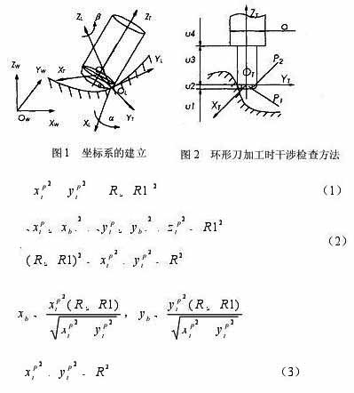
When the feature point P is within the range of u1, no interference will occur.
When the characteristic point P is in the range of u2, there are two situations, and the torus is divided into two parts:
The small cylindrical part P1 and the circular ring part P2. When the feature point is involved in the cylindrical part P1, tool interference occurs, that is, it is satisfied
where R represents the radius of the tool, and R1 represents the radius of the ring of the circular tool.
When the feature point is involved in the ring part P2, tool interference also occurs, that is, it is satisfied
in the style
If the feature point P does not enter the parts P1 and P2, no tool interference will occur.
When the characteristic point P is within the range of u3, when the distance between the characteristic point P and the ZT axis is less than the tool radius, tool interference occurs, which is satisfied
Otherwise, no tool interference will occur.
When the characteristic point P is in the range of u4, the situation is the same as that of 3, as long as the tool radius R in the formula (3) is replaced with the power head radius d/2 for judgment.
The feature projection method is suitable for 5-axis CNC machining tool interference processing, that is, the machining surface is discretized into a series of surface feature points. Whether the tool interference occurs can be judged by whether the feature point enters the inside of the tool surface. At the same time, the machining surface and the tool surface are projected onto a specific plane, and only the feature detection points in the curved surface area of the enveloping tool projection graph are checked for interference, which improves the efficiency of interference detection.
1. Inspection method for tool interference
Coordinate system and coordinate transformation
As shown in Figure 1, the local coordinate system L of 5-axis circular cutter milling is represented as XL axis, YL axis and ZL axis. The YL axis always points to the cutting direction f of the tool contact (referred to as CC point) OL. The ZL axis points to the normal direction n of the surface, and the XL axis is determined by the right-hand rule of the YL axis and the ZL axis. The tool generally rotates around the XL axis from the ZL axis to the YL axis by a lead angle (heel angle) a, and rotates around the ZL axis one by one side slip angle b. In addition, the tool coordinate system T (XT, YT, ZT) can also be defined at the tool location point (CL point for short) OT. The YT axis points to the direction of the line connecting the CL point and the CC point. The ZT axis is the tool axis vector direction, and the XT axis is the direction determined by the right-hand rule of the YT axis and the ZT axis. The coordinate origin is located at the tool center point (ie CL point) OT. In order to simplify the interference check, the tool surface with a relatively regular shape is used as the reference for interference check. The machined surface is discretized to express the shape of the surface in the form of a set of characteristic points. The original data of these feature points are expressed in the world coordinate system W, so the feature point data must first be transformed from the world coordinate system W (OW-XW, YW, ZW) to the local coordinate system L (OL-XL, YL, ZL) ). It is then transformed from the local coordinate system L to the tool coordinate system T (OT-XT, YT, ZT).
Interference check method
If the tool and power head have been selected, the size of the tool system (tool and power head) is known. Whether the tool system interferes with the machined surface can be determined by judging whether the characteristic point P enters the inside of the tool surface. As shown in Figure 2, it is the positional relationship between the tool system and the machined surface when the ring knife is processed. In the tool coordinate system, let the coordinate of the characteristic point P be PI (Xpt, Ypt, Zpt). According to the different combination parts of the tool system, the coordinate value Zpt of the characteristic point P is divided into 4 sections for judgment. Details are as follows:
When the feature point P is within the range of u1, no interference will occur.
When the characteristic point P is in the range of u2, there are two situations, and the torus is divided into two parts:
The small cylindrical part P1 and the circular ring part P2. When the feature point is involved in the cylindrical part P1, tool interference occurs, that is, it is satisfied
where R represents the radius of the tool, and R1 represents the radius of the ring of the circular tool.
When the feature point is involved in the ring part P2, tool interference also occurs, that is, it is satisfied
in the style
If the feature point P does not enter the parts P1 and P2, no tool interference will occur.
When the characteristic point P is within the range of u3, when the distance between the characteristic point P and the ZT axis is less than the tool radius, tool interference occurs, which is satisfied
Otherwise, no tool interference will occur.
When the characteristic point P is in the range of u4, the situation is the same as that of 3, as long as the tool radius R in the formula (3) is replaced with the power head radius d/2 for judgment.


