5-axis machining of complex profiles
Complex contours appear in tool and mold manufacturing, and are mass-produced products. Before the emergence of CNC machine tools, forging dies and dies used in the automotive industry were mainly manufactured by hand. After the 1970s, CNC machine tools have been widely used in tool and mold manufacturing. The basic contours of complex profiles are usually processed by milling, and the surrounding CNC machine tools are initially set to three-axis linkage.
After entering the 1980s, five-axis milling machines have been widely used in complex surface processing. The contour of the workpiece after milling is very close to the final shape of the workpiece, but the last finishing process is still manual. In the late 1980s, high-speed cutting technology gradually developed and matured, and its application in industrial production has been continuously improved in terms of machine tools, cutting tools and other related technologies. Since high-speed cutting can double the feed speed, the feed pitch can be reduced without reducing production efficiency. This provides a prerequisite for improving the shape accuracy of the workpiece and reducing the surface roughness. At present, most of the workpieces processed by high-speed milling no longer need the last manual processing procedure, but can be directly put into use.
New tool materials: such as alumina-based ceramics, silicon nitride-based ceramics, cermets, cemented carbide, especially the continuous development of superhard coatings, making hard face milling possible. The mold surface can be milled to shape after quenching, thereby avoiding deformation caused by quenching after milling. This not only simplifies the machining process, but also improves the accuracy of the workpiece.
In addition, with the application of precision forging in die manufacturing, the die blank after forging already has its designed basic shape, and the remaining machining allowance is insignificant compared with the milling of the entire blank. In this case, in addition to milling, it can also be processed by high-efficiency grinding. Compared with hard face milling, high-efficiency grinding can not only improve the shape accuracy of the workpiece, but also improve the surface roughness of the workpiece. There are many high-efficiency grinding methods, usually high-speed grinding with spherical grinding wheels and belt grinding with small-diameter belt wheels.
Three-dimensional free-form surfaces in tools and molds are usually processed on a 5-axis machining center. Since the material of the workpiece is mostly alloy steel or tool steel, the structure of the machine tool and the numerical control system must consider the requirements of productivity and workpiece accuracy in the processing process, and make appropriate layout and optimization based on this. In order to ensure that the machine tool does not undergo too much deformation when cutting various mold materials, the machine tool stiffness should be the first priority when determining the machine layout. Larger axis machining center, most of a gantry structure, some small-sized five-axis machining center is also sometimes used high column structure.
Since the beginning of the 1990s, almost all complex shapes have been processed by high-speed cutting in production. The purpose is to improve production efficiency, reduce product cost, and at the same time improve the shape accuracy of the workpiece and reduce the surface roughness. In order to meet the needs of high-speed cutting, the spindle of the machine tool almost without exception uses an electric spindle. The spindle speed is continuously variable according to the diameter of the tool used, and the speed ranges from several thousand revolutions per minute to tens of thousands of revolutions per minute. The drive system of the sliding table is also different from conventional machining centers in high-speed cutting. Commonly used system with high-speed drive nut screw assembly and linear motor drive, a maximum feed speed can reach 100m / min or more.
When processing complex surfaces, the CNC system of the machine tool must also meet some special requirements. For example, CNC machining programs for complex surfaces are generally generated on CAD/CAM software. A profiled program often requires several megabytes (Byte) of storage space, and it is no longer possible to transfer NC programs with a floppy disk. Therefore, the CNC system must have the function of networking with other computer systems in order to receive the CNC program directly from the CAD/CAM. In addition, the numerical control system must also adopt advanced control technology, first of all, it requires the function of LookAhead. In other words, before the machine tool processes a certain track, the data system analyzes the surface to be processed in advance. According to the curvature of each point of the curved surface and the connection relationship of each adjacent point, the feed speed of the machine tool is appropriately adjusted to achieve the highest productivity under the premise of ensuring the accuracy of the workpiece. In order to reduce dynamic errors during processing, the new servo error correcting data using a conventional tandem system is no longer proportional integral derivative (PID) controller, instead of using the state regulator by compensating for the position and speed state parameters. Using this kind of regulator can completely eliminate the drive hysteresis error, compensate for the nonlinear error caused by the gap or friction, and even offset certain vibrations of the machine tool. So as to meet the requirements of improving the shape accuracy of the workpiece and reducing the surface roughness.
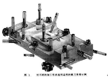
The tool system plays a decisive role in the production efficiency and processing quality when processing complex profiles. When selecting a cutting tool system, we must first start from the geometry of the parts to be processed, and reasonably use the types of cutting tools. As shown in Figure 1, the geometry of each part is very different. If only a ball-end milling cutter is used for processing, a ball-end milling cutter with a small diameter must be selected, which makes it difficult to improve processing efficiency. In addition, the arc radius of some parts is so small that it cannot be processed even with a small ball end mill. Therefore, taking into account the requirements of both production efficiency and workpiece shape, other types of milling cutters must be equipped on the five-axis machining center for processing complex profiles, such as end mills and three-face milling cutters.
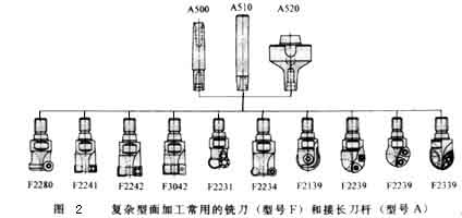
Figure 2 shows some types of milling cutters. As long as the size permits, regardless of the shape of the tool, the cutting edge should be a milling insert with a convertible clamp. Such knives can be combined in a variety of ways because of the blade and the body, and the blade and the body can be produced by different companies. Therefore, large-scale specialized production can be formed, which not only helps to improve the quality of the tool, but also helps to reduce the production cost of the tool.
Currently, most of the indexable blades on the market use CVD coated carbide blades. In order to achieve higher pseudo-abrasion resistance, the indexable inserts are all multi-layered coatings. Bizhi Al2O3 can improve the chemical stability of the blade. TiN and TiCN can enhance the wear resistance of the blade. In order to enhance the sharpness of the blade, in addition to the low-temperature CVD method, the coating can also be produced by the PVD method. Some processing has very strict requirements on the blade. The blade must have a sharp cutting edge to reduce the roughness of the finished surface, but also have a high wear resistance to ensure the shape accuracy of the workpiece. In this case, a combination of multiple coatings must be used. In order to ensure that the use of some blades is foolproof, the number of coating layers can be as high as 100.
The life of the tool is closely related to the feed rate, cutting speed and depth of cut. The optimal cutting amount is often a small range, which should be determined according to the specific tool and workpiece material.
In addition, cutting strategies such as: The planning of the tool path, the normal vector of the tool axis surface (the normal direction of the surface at this point) or the different methods along the surface tangent vector (the tangent direction of the surface at this point), etc., are also a key factor for processing complex surfaces . It not only affects the surface roughness of the processed workpiece, but also affects the shape and dimensional accuracy of the workpiece. Figure 3 shows the different cutting strategies used when machining a cylindrical surface. For cutting in the circumferential direction, the tool path needs to be interpolated in two-axis linkage. When cutting along the generatrix direction, the tool only needs to perform single-axis interpolation. In addition, different cutting methods have great differences in tool wear. The tool wear during down milling is significantly lower than that of up milling, and the wear during reciprocating milling is much greater than that of unidirectional milling.
In order to improve the stability of the machining process, when optimizing the cutting strategy, the continuity of the cutting must be ensured, and the cutting motion and idle stroke must be reduced as much as possible in order to shorten the cutting time. When the rough milling of steel, must ensure continuous climb milling, to minimize the peak of the cutting blade during cutting of the amount of fluctuation.
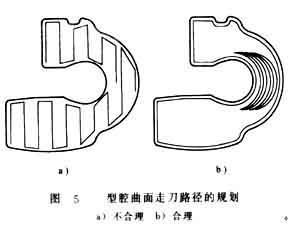
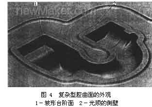
When processing the workpiece shown in Figure 4, if the row cut trajectory section processing shown in Figure 5a is used; The movement of the tool is very unreasonable, the cutting conditions are very unsatisfactory, the processing time is 33min, and the surface roughness of the workpiece is 6-9μm. If you switch to the circle-cutting path shown in Figure 5b for processing, the processing time is about 27 minutes. At the same time, the roughness of the workpiece can also be reduced to 2 ~ 4μm.
After entering the 1980s, five-axis milling machines have been widely used in complex surface processing. The contour of the workpiece after milling is very close to the final shape of the workpiece, but the last finishing process is still manual. In the late 1980s, high-speed cutting technology gradually developed and matured, and its application in industrial production has been continuously improved in terms of machine tools, cutting tools and other related technologies. Since high-speed cutting can double the feed speed, the feed pitch can be reduced without reducing production efficiency. This provides a prerequisite for improving the shape accuracy of the workpiece and reducing the surface roughness. At present, most of the workpieces processed by high-speed milling no longer need the last manual processing procedure, but can be directly put into use.
New tool materials: such as alumina-based ceramics, silicon nitride-based ceramics, cermets, cemented carbide, especially the continuous development of superhard coatings, making hard face milling possible. The mold surface can be milled to shape after quenching, thereby avoiding deformation caused by quenching after milling. This not only simplifies the machining process, but also improves the accuracy of the workpiece.
In addition, with the application of precision forging in die manufacturing, the die blank after forging already has its designed basic shape, and the remaining machining allowance is insignificant compared with the milling of the entire blank. In this case, in addition to milling, it can also be processed by high-efficiency grinding. Compared with hard face milling, high-efficiency grinding can not only improve the shape accuracy of the workpiece, but also improve the surface roughness of the workpiece. There are many high-efficiency grinding methods, usually high-speed grinding with spherical grinding wheels and belt grinding with small-diameter belt wheels.
Three-dimensional free-form surfaces in tools and molds are usually processed on a 5-axis machining center. Since the material of the workpiece is mostly alloy steel or tool steel, the structure of the machine tool and the numerical control system must consider the requirements of productivity and workpiece accuracy in the processing process, and make appropriate layout and optimization based on this. In order to ensure that the machine tool does not undergo too much deformation when cutting various mold materials, the machine tool stiffness should be the first priority when determining the machine layout. Larger axis machining center, most of a gantry structure, some small-sized five-axis machining center is also sometimes used high column structure.
Since the beginning of the 1990s, almost all complex shapes have been processed by high-speed cutting in production. The purpose is to improve production efficiency, reduce product cost, and at the same time improve the shape accuracy of the workpiece and reduce the surface roughness. In order to meet the needs of high-speed cutting, the spindle of the machine tool almost without exception uses an electric spindle. The spindle speed is continuously variable according to the diameter of the tool used, and the speed ranges from several thousand revolutions per minute to tens of thousands of revolutions per minute. The drive system of the sliding table is also different from conventional machining centers in high-speed cutting. Commonly used system with high-speed drive nut screw assembly and linear motor drive, a maximum feed speed can reach 100m / min or more.
When processing complex surfaces, the CNC system of the machine tool must also meet some special requirements. For example, CNC machining programs for complex surfaces are generally generated on CAD/CAM software. A profiled program often requires several megabytes (Byte) of storage space, and it is no longer possible to transfer NC programs with a floppy disk. Therefore, the CNC system must have the function of networking with other computer systems in order to receive the CNC program directly from the CAD/CAM. In addition, the numerical control system must also adopt advanced control technology, first of all, it requires the function of LookAhead. In other words, before the machine tool processes a certain track, the data system analyzes the surface to be processed in advance. According to the curvature of each point of the curved surface and the connection relationship of each adjacent point, the feed speed of the machine tool is appropriately adjusted to achieve the highest productivity under the premise of ensuring the accuracy of the workpiece. In order to reduce dynamic errors during processing, the new servo error correcting data using a conventional tandem system is no longer proportional integral derivative (PID) controller, instead of using the state regulator by compensating for the position and speed state parameters. Using this kind of regulator can completely eliminate the drive hysteresis error, compensate for the nonlinear error caused by the gap or friction, and even offset certain vibrations of the machine tool. So as to meet the requirements of improving the shape accuracy of the workpiece and reducing the surface roughness.
The tool system plays a decisive role in the production efficiency and processing quality when processing complex profiles. When selecting a cutting tool system, we must first start from the geometry of the parts to be processed, and reasonably use the types of cutting tools. As shown in Figure 1, the geometry of each part is very different. If only a ball-end milling cutter is used for processing, a ball-end milling cutter with a small diameter must be selected, which makes it difficult to improve processing efficiency. In addition, the arc radius of some parts is so small that it cannot be processed even with a small ball end mill. Therefore, taking into account the requirements of both production efficiency and workpiece shape, other types of milling cutters must be equipped on the five-axis machining center for processing complex profiles, such as end mills and three-face milling cutters.
Figure 2 shows some types of milling cutters. As long as the size permits, regardless of the shape of the tool, the cutting edge should be a milling insert with a convertible clamp. Such knives can be combined in a variety of ways because of the blade and the body, and the blade and the body can be produced by different companies. Therefore, large-scale specialized production can be formed, which not only helps to improve the quality of the tool, but also helps to reduce the production cost of the tool.
Currently, most of the indexable blades on the market use CVD coated carbide blades. In order to achieve higher pseudo-abrasion resistance, the indexable inserts are all multi-layered coatings. Bizhi Al2O3 can improve the chemical stability of the blade. TiN and TiCN can enhance the wear resistance of the blade. In order to enhance the sharpness of the blade, in addition to the low-temperature CVD method, the coating can also be produced by the PVD method. Some processing has very strict requirements on the blade. The blade must have a sharp cutting edge to reduce the roughness of the finished surface, but also have a high wear resistance to ensure the shape accuracy of the workpiece. In this case, a combination of multiple coatings must be used. In order to ensure that the use of some blades is foolproof, the number of coating layers can be as high as 100.
The life of the tool is closely related to the feed rate, cutting speed and depth of cut. The optimal cutting amount is often a small range, which should be determined according to the specific tool and workpiece material.
In addition, cutting strategies such as: The planning of the tool path, the normal vector of the tool axis surface (the normal direction of the surface at this point) or the different methods along the surface tangent vector (the tangent direction of the surface at this point), etc., are also a key factor for processing complex surfaces . It not only affects the surface roughness of the processed workpiece, but also affects the shape and dimensional accuracy of the workpiece. Figure 3 shows the different cutting strategies used when machining a cylindrical surface. For cutting in the circumferential direction, the tool path needs to be interpolated in two-axis linkage. When cutting along the generatrix direction, the tool only needs to perform single-axis interpolation. In addition, different cutting methods have great differences in tool wear. The tool wear during down milling is significantly lower than that of up milling, and the wear during reciprocating milling is much greater than that of unidirectional milling.
In order to improve the stability of the machining process, when optimizing the cutting strategy, the continuity of the cutting must be ensured, and the cutting motion and idle stroke must be reduced as much as possible in order to shorten the cutting time. When the rough milling of steel, must ensure continuous climb milling, to minimize the peak of the cutting blade during cutting of the amount of fluctuation.


