Turning and Milling Hollow Parts Clamping
Unlike normal workpiece turning and milling operations, the clamping of thin-walled hollow workpieces requires the use of a chuck with low distortion and safety. When turning thin-walled hollow parts, clamping distortion can cause the specified tolerance range to be exceeded and the workpiece to become scrap. The choice of chuck is therefore very important. Balanced clamping jaws offer the advantage that, with an optimum arrangement of the clamping points, the deformation of the workpiece can be reduced to 10% of the original deformation, while the clamping force of the chuck remains constant.
A problem that tends to arise when turning or milling thin-walled hollow parts is the deformation of the workpiece by the clamping force of the chuck. Workpieces such as rings or box housings must be held firmly so that they do not loosen even under cutting forces. Very strong clamping forces will inevitably cause workpiece deformation, the amount of which depends on the shape and wall thickness of the workpiece. At the same time, the material also plays a very important role. Cast iron, brass, bronze and aluminium alloy parts are more fragile than steel parts due to their lower modulus of elasticity. Particularly when turning mating workpieces, clamping distortion can cause the given tolerance range to be exceeded and lead to scrap.
By marking the arrangement of the chuck on the turned workpiece, the clamped workpiece will normally still appear intact and round on the machine after the turning process. Thin-walled workpieces, after clamping, have a more or less non-circular shape, which can be clearly observed by means of a rounding tool. The distribution of the chuck must therefore be marked on the workpiece so that it can be identified whether the clamping force has caused any deformation.
Fig. 1. Free clamping of material can lead to irregular shape errors
Figures 1 and 2 show in a simple way the various causes of roundness defects due to turning and milling. Irregular shape errors can also occur during the stress relief of castings, which is important in relation to special workpiece shapes with local material build-up. A clear delineation of roundness errors and clamping positions is not possible. Trial turning, slackening and finishing of harsh part surfaces, or free annealing of raw workpieces prior to machining, will help to improve the quality of the workpiece.
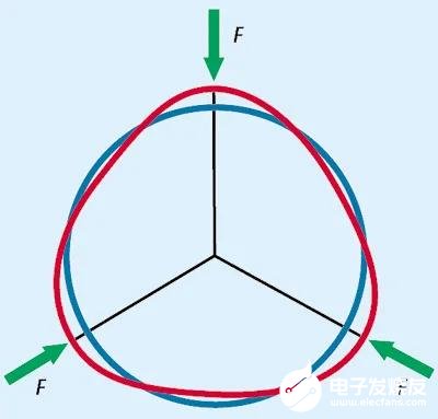
Figure 2: Regular deformation by the chuck clamping force
In the example of Fig. 2, the workpiece is clearly deformed by the chuck clamping force and its bore is somewhat squeezed inward in the chuck area. As a result, there is a situation where too much material is ground at this location after the workpiece is released and withdrawn. The simplest solution is to consider reducing the clamping pressure. In this regard, attention must be paid to whether the chuck still has sufficient clamping force in this condition, since the grinding process usually requires high cutting speeds and rotational speeds. In the absence of centrifugal force balance, the clamping force can easily drop to dangerous levels. Therefore, the requirements of the CNC manufacturer for measuring the chuck clamping force at operating speed must be strictly observed.
I. Roundness measurement reflects the cause of error
Not only the two sources of error are clearly different from each other, roundness measurement also often shows some kind of mixed shape between the two situations. It can provide information about the cause of the error source so that remedial measures can be taken.
Fig. 3, Power chuck QLC-KT with rigid caliper
If the reduction of the clamping force does not bring satisfactory results, an analysis of the used chuck can be recommended. For example, workpieces of box housing parts of cast iron are often clamped with a hard standard stepped chuck (Fig. 3). The chuck teeth on its clamping surface gradually become blunt due to natural wear after a longer period of use, and the clamping and fastening effect is weakened. The risk of workpiece slippage or dislodgement from the chuck during machining increases gradually.
Figure 4, KBNKLA jaw chuck (a) and sector chuck (b) with higher safety
II. Hard Step Chuck
Every CNC machining company is able to maintain a stock of hardened step chucks. This would be a good thing to do, as the cost would be much lower than the cost of losing the workpiece during machining. The new chucks require less clamping force and therefore less deformation of the workpiece due to their good clamping effect. Jaw chucks with tapered teeth (Fig. 4) can provide greater safety. These chucks can grip the surface of the workpiece and achieve double the cutting force with the same clamping force as a step chuck with one tooth for paving blocks, while requiring less investment and contributing to better quality and process safety. Chuck manufacturers can provide these chucks in various shapes and sizes. The swing jaw chuck offers particular advantages when clamping sensitive raw material workpieces (Figure 5). The swing bridge distributes the clamping force to double the number of clamping points, each of which is subjected to only half the force, and the bending elastic range between the clamping points on the workpiece is reduced. If the distribution of the clamping points is optimal (evenly distributed around the circumference), the deformation of the workpiece can be reduced to approximately 10% of the original deformation without reducing the clamping force of the chuck.
Fig. 5, Chuck with swing jaws (b) (a)
In the case of clamping on the diameter of a workpiece that has already been turned, a hard chuck with a wider range of applications can be used (Fig. 6). The screwed-in clamping diameter supports the workpiece over the entire circumference, so that the workpiece is not deformed even under higher clamping forces. This type of chuck can be supplied by different manufacturers and is a special shape, which can be optimally designed and manufactured according to the workpiece drawing.
Fig. 6, Power chuck with large scale clamps for clamping on already turned and milled workpiece diameters
For CNC machining of large quantities of identical or similar workpieces, special clamping devices can be used. Especially for thin-walled rings, good results can be obtained with mechanically driven lever-balanced chucks with 6 or 12 chucks with diameters of 400 to 4000 mm (Fig. 7). An equalization of clamping volume and clamping force is created between the individual chucks, so that the workpiece can be held safely and without deformation even if there is an error in the circumference of the workpiece. In addition, the fixture can be switched manually and automatically to a purely central clamping method.
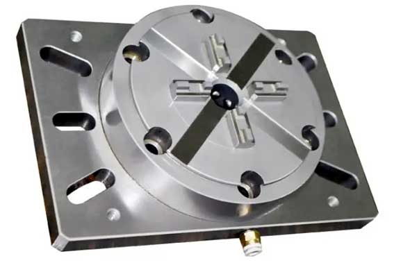
Fig. 7, A six-caliper lever balance chuck of type 6WAZM with a fast adjustable caliper clamping a thin-walled ring can be obtained with good results.
III. Clamping force axially acting on the support
For particularly easily deformed and irregularly shaped workpieces, finger chucks are usually used. In this case, the clamping force does not act radially, but axially by the finger chuck on the set centering and support points (Figure 8), and the radial deformation of the workpiece is avoided to the greatest extent. In finger chucks, it is possible to combine the previous alignment chucks with smaller clamping forces and strong axial clamping. In addition, there are many special chucks that can be used not only for annular workpieces, but also for workpieces of various complex shapes.
Fig. 8, mechanically driven FLDA type centering finger chucks are especially used for workpieces that are easily deformed and irregularly shaped
Most of these chucks are designed for specific shapes of workpieces and are designed and manufactured by specialized clamping technology companies according to customer orders. Of course, this type of chuck is more expensive than the standard fixture for batch processing, but it can greatly improve the quality and productivity of the process and pay for itself in a shorter period of time.
A problem that tends to arise when turning or milling thin-walled hollow parts is the deformation of the workpiece by the clamping force of the chuck. Workpieces such as rings or box housings must be held firmly so that they do not loosen even under cutting forces. Very strong clamping forces will inevitably cause workpiece deformation, the amount of which depends on the shape and wall thickness of the workpiece. At the same time, the material also plays a very important role. Cast iron, brass, bronze and aluminium alloy parts are more fragile than steel parts due to their lower modulus of elasticity. Particularly when turning mating workpieces, clamping distortion can cause the given tolerance range to be exceeded and lead to scrap.
By marking the arrangement of the chuck on the turned workpiece, the clamped workpiece will normally still appear intact and round on the machine after the turning process. Thin-walled workpieces, after clamping, have a more or less non-circular shape, which can be clearly observed by means of a rounding tool. The distribution of the chuck must therefore be marked on the workpiece so that it can be identified whether the clamping force has caused any deformation.
Fig. 1. Free clamping of material can lead to irregular shape errors
Figures 1 and 2 show in a simple way the various causes of roundness defects due to turning and milling. Irregular shape errors can also occur during the stress relief of castings, which is important in relation to special workpiece shapes with local material build-up. A clear delineation of roundness errors and clamping positions is not possible. Trial turning, slackening and finishing of harsh part surfaces, or free annealing of raw workpieces prior to machining, will help to improve the quality of the workpiece.
Figure 2: Regular deformation by the chuck clamping force
In the example of Fig. 2, the workpiece is clearly deformed by the chuck clamping force and its bore is somewhat squeezed inward in the chuck area. As a result, there is a situation where too much material is ground at this location after the workpiece is released and withdrawn. The simplest solution is to consider reducing the clamping pressure. In this regard, attention must be paid to whether the chuck still has sufficient clamping force in this condition, since the grinding process usually requires high cutting speeds and rotational speeds. In the absence of centrifugal force balance, the clamping force can easily drop to dangerous levels. Therefore, the requirements of the CNC manufacturer for measuring the chuck clamping force at operating speed must be strictly observed.
I. Roundness measurement reflects the cause of error
Not only the two sources of error are clearly different from each other, roundness measurement also often shows some kind of mixed shape between the two situations. It can provide information about the cause of the error source so that remedial measures can be taken.
Fig. 3, Power chuck QLC-KT with rigid caliper
If the reduction of the clamping force does not bring satisfactory results, an analysis of the used chuck can be recommended. For example, workpieces of box housing parts of cast iron are often clamped with a hard standard stepped chuck (Fig. 3). The chuck teeth on its clamping surface gradually become blunt due to natural wear after a longer period of use, and the clamping and fastening effect is weakened. The risk of workpiece slippage or dislodgement from the chuck during machining increases gradually.
Figure 4, KBNKLA jaw chuck (a) and sector chuck (b) with higher safety
II. Hard Step Chuck
Every CNC machining company is able to maintain a stock of hardened step chucks. This would be a good thing to do, as the cost would be much lower than the cost of losing the workpiece during machining. The new chucks require less clamping force and therefore less deformation of the workpiece due to their good clamping effect. Jaw chucks with tapered teeth (Fig. 4) can provide greater safety. These chucks can grip the surface of the workpiece and achieve double the cutting force with the same clamping force as a step chuck with one tooth for paving blocks, while requiring less investment and contributing to better quality and process safety. Chuck manufacturers can provide these chucks in various shapes and sizes. The swing jaw chuck offers particular advantages when clamping sensitive raw material workpieces (Figure 5). The swing bridge distributes the clamping force to double the number of clamping points, each of which is subjected to only half the force, and the bending elastic range between the clamping points on the workpiece is reduced. If the distribution of the clamping points is optimal (evenly distributed around the circumference), the deformation of the workpiece can be reduced to approximately 10% of the original deformation without reducing the clamping force of the chuck.
Fig. 5, Chuck with swing jaws (b) (a)
In the case of clamping on the diameter of a workpiece that has already been turned, a hard chuck with a wider range of applications can be used (Fig. 6). The screwed-in clamping diameter supports the workpiece over the entire circumference, so that the workpiece is not deformed even under higher clamping forces. This type of chuck can be supplied by different manufacturers and is a special shape, which can be optimally designed and manufactured according to the workpiece drawing.
Fig. 6, Power chuck with large scale clamps for clamping on already turned and milled workpiece diameters
For CNC machining of large quantities of identical or similar workpieces, special clamping devices can be used. Especially for thin-walled rings, good results can be obtained with mechanically driven lever-balanced chucks with 6 or 12 chucks with diameters of 400 to 4000 mm (Fig. 7). An equalization of clamping volume and clamping force is created between the individual chucks, so that the workpiece can be held safely and without deformation even if there is an error in the circumference of the workpiece. In addition, the fixture can be switched manually and automatically to a purely central clamping method.
Fig. 7, A six-caliper lever balance chuck of type 6WAZM with a fast adjustable caliper clamping a thin-walled ring can be obtained with good results.
III. Clamping force axially acting on the support
For particularly easily deformed and irregularly shaped workpieces, finger chucks are usually used. In this case, the clamping force does not act radially, but axially by the finger chuck on the set centering and support points (Figure 8), and the radial deformation of the workpiece is avoided to the greatest extent. In finger chucks, it is possible to combine the previous alignment chucks with smaller clamping forces and strong axial clamping. In addition, there are many special chucks that can be used not only for annular workpieces, but also for workpieces of various complex shapes.
Fig. 8, mechanically driven FLDA type centering finger chucks are especially used for workpieces that are easily deformed and irregularly shaped
Most of these chucks are designed for specific shapes of workpieces and are designed and manufactured by specialized clamping technology companies according to customer orders. Of course, this type of chuck is more expensive than the standard fixture for batch processing, but it can greatly improve the quality and productivity of the process and pay for itself in a shorter period of time.
PREV:Boring and Milling Supplier of Precision Components
NEXT:NONE
NEXT:NONE


