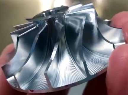
5-axis machining of complex curved parts
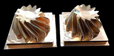
5-axis machining of complex curved parts (aluminum alloy, stainless steel, copper, titanium, magnesium, copper)
Several elements of 5-axis machining of complex curved parts: curved surfaces and indexable milling inserts generated on CAD/CAM software
Almost all complex curved surfaces are processed by high-speed milling in production. The purpose is to improve production efficiency, reduce product cost, and at the same time improve the shape accuracy of the workpiece and reduce the surface roughness. In order to meet the needs of high-speed milling, the spindle of the machine tool almost without exception uses an electric spindle. The spindle speed is continuously variable according to the diameter of the tool used, and the speed range is from several thousand revolutions per minute to tens of thousands of revolutions per minute. The drive system of the sliding table is also different from conventional machining centers in high-speed milling. Commonly used systems include high-speed screw nut pair drive and linear motor drive, and the maximum feed speed can reach more than 100m/min.
When processing complex curved surfaces, the CNC system of the machine tool must also meet some special requirements. For example, NC machining programs for complex curved surfaces are generally generated on CAD/CAM software. A curved surface program often requires several megabytes (Byte) of storage space, and it is no longer possible to transfer the NC program with a floppy disk. Therefore, the numerical control system must have the function of networking with other computer systems in order to directly receive numerical control programs from CAD/CAM. In addition, the numerical control system must also adopt advanced control technology, first of all, it requires the look-ahead (LookAhead) function. In other words, before the machine tool processes a certain track, the data system analyzes the surface to be processed in advance, according to the curvature of each point on the surface and the connection relationship between adjacent points. Properly adjust the feed speed of the machine tool to achieve the highest productivity while ensuring the accuracy of the workpiece. In order to reduce the dynamic error in the machining process, the new type of data system servo error correction no longer uses the previous series proportional differential integral (PID) regulator. Instead, it uses a state regulator that compensates for state parameters such as position and speed. The use of this regulator can completely eliminate the drive lag error, compensate for the nonlinear error caused by the gap or friction, and even offset certain vibrations of the machine tool. So as to meet the requirements of improving the shape accuracy of the workpiece and reducing the surface roughness.
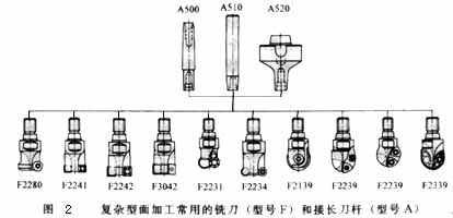
Figure 2 shows some of the selected milling cutter types. As long as the size permits, regardless of the shape of the milling tool, the cutting edge should be a machine-clamped indexable milling insert. Such knives can be combined with blades and bodies, and the blades and bodies can be produced by different companies. Therefore, a large-scale specialized production can be formed, which is not only conducive to improving the quality of the tool, but also conducive to reducing the production cost of the tool.
The tool life is closely related to the feed rate, cutting speed and milling depth. The optimal milling amount is often a small range, which should be determined according to the specific tool and workpiece material.
In addition, cutting strategies such as: Tool path planning, tool axis surface normal vector (the surface normal direction at this point) or along the surface tangent vector (surface tangent direction at this point) is also a key factor for processing complex surfaces. It not only affects the surface roughness of the processed workpiece, but also affects the shape and dimensional accuracy of the workpiece. Figure 3 shows the different cutting strategies used when machining a cylindrical curved surface. For milling in the circumferential direction, the tool path needs to be interpolated with two-axis linkage. When cutting along the generatrix direction, the tool only needs to perform single-axis interpolation. In addition, different cutting methods have great differences in tool wear: The tool wear during down milling is significantly lower than that of up-down milling, and the wear during reciprocating milling is much greater than that of unidirectional milling.
In order to improve the stability of the machining process, the continuity of cutting must be ensured when optimizing the cutting strategy. At the same time, reduce the cutting motion and idle stroke as much as possible to shorten the milling time. When rough milling steel parts, it is necessary to ensure continuous down milling to minimize the peak value of the cutting edge during the cutting process.
When processing the workpiece shown in Figure 4, if the row cutting and milling track shown in Figure 5a is used for partition processing; The movement of the tool is very unreasonable, the cutting conditions are very unsatisfactory, the machining time is 33min, and the surface roughness of the workpiece is 6-9μm. If the circle cutting track shown in Figure 5b is used instead for processing, the processing time is about 27 minutes, and the roughness of the workpiece can also be reduced to 2 to 4 μm.


