How to understand complicated CNC machining parts drawings
We welcome your part drawing and sample. Our company will quickly analyze your drawings and give a reasonable CNC machining method and quotation.
If you are a professional of CNC machine tool processing, it is not difficult to understand the professional dimensions and symbols on the drawings of precision metal parts processing. But if you are initially exposed to the CNC machining industry, or you need to develop a project, the dazzling drawings may make you very painful. If you do not understand the drawings, the efficiency and effectiveness of many things will be difficult to guarantee. Today we will learn how to understand the processing drawings of precision metal parts:
Understand the CNC machining drawings of the parts, determine the appropriate CNC machining method, and evaluate the price of the machined parts.
1. The size notation method of common structures
Common hole size injection method (blind hole, threaded hole, counterbore, countersink hole); size annotation method for chamfer.
Blind hole
Threaded hole
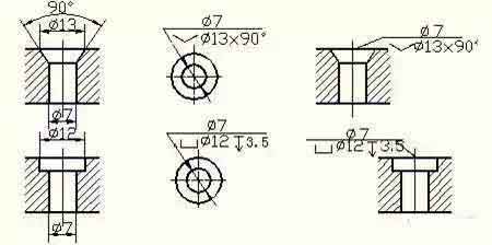
Counterbore
Countersunk hole
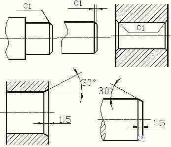
Chamfer
2. Machining structure on parts
Design of undercut and overtravel grooves for CNC machining
In the CNC machining of parts, in order to facilitate the withdrawal of the tool and ensure that the contact surfaces of the relevant parts are tight during assembly. The undercut or overtravel groove of the grinding wheel should be machined in advance at the step of the machined surface.
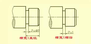
The size of the undercut when turning the outer circle can generally be marked in the way of "groove width × diameter" or "groove width × groove depth". Grinding wheel overtravel grooves when grinding external circles and end faces.
Drilling structure
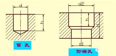
The blind hole drilled with a drill has a cone angle of 120° at the bottom. It refers to the depth of the drilling depth of the cylindrical portion, excluding cone pit. At the transition of stepped boreholes, there is also a cone angle of 120° frustum, its drawing method and size injection method.
When drilling with a drill bit, the axis of the drill bit is required to be as perpendicular to the end face of the drilled hole as possible to ensure the accuracy of the drilling and avoid the drill bit from breaking. The correct structure of the three drilling end faces.
Bosses and pits
The contact surface parts and other parts, are generally required processing. In order to reduce the processing area and ensure good contact between the surface of the parts, bosses and pits are often designed on the castings. The form of the supporting surface boss or the supporting surface pit of the bolt connection;
In order to reduce the CNC machining area, a groove structure is made.
If you are a professional of CNC machine tool processing, it is not difficult to understand the professional dimensions and symbols on the drawings of precision metal parts processing. But if you are initially exposed to the CNC machining industry, or you need to develop a project, the dazzling drawings may make you very painful. If you do not understand the drawings, the efficiency and effectiveness of many things will be difficult to guarantee. Today we will learn how to understand the processing drawings of precision metal parts:
Understand the CNC machining drawings of the parts, determine the appropriate CNC machining method, and evaluate the price of the machined parts.
1. The size notation method of common structures
Common hole size injection method (blind hole, threaded hole, counterbore, countersink hole); size annotation method for chamfer.
Blind hole
Threaded hole
Counterbore
Countersunk hole
Chamfer
2. Machining structure on parts
Design of undercut and overtravel grooves for CNC machining
In the CNC machining of parts, in order to facilitate the withdrawal of the tool and ensure that the contact surfaces of the relevant parts are tight during assembly. The undercut or overtravel groove of the grinding wheel should be machined in advance at the step of the machined surface.
The size of the undercut when turning the outer circle can generally be marked in the way of "groove width × diameter" or "groove width × groove depth". Grinding wheel overtravel grooves when grinding external circles and end faces.
Drilling structure
The blind hole drilled with a drill has a cone angle of 120° at the bottom. It refers to the depth of the drilling depth of the cylindrical portion, excluding cone pit. At the transition of stepped boreholes, there is also a cone angle of 120° frustum, its drawing method and size injection method.
When drilling with a drill bit, the axis of the drill bit is required to be as perpendicular to the end face of the drilled hole as possible to ensure the accuracy of the drilling and avoid the drill bit from breaking. The correct structure of the three drilling end faces.
Bosses and pits
The contact surface parts and other parts, are generally required processing. In order to reduce the processing area and ensure good contact between the surface of the parts, bosses and pits are often designed on the castings. The form of the supporting surface boss or the supporting surface pit of the bolt connection;
In order to reduce the CNC machining area, a groove structure is made.


