Drawings and Quote of several conventional turning and milling parts
Common CNC machining precision parts structure drawings and Quote : shaft and sleeve parts; plate and cover parts; fork frame parts; aluminum box and cavity parts; free-form surface parts.
Shaft and sleeve parts
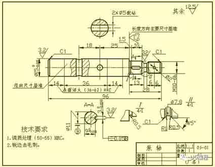
Such parts generally include shafts, bushings and other parts. When expressing views, as long as you draw a basic view and add appropriate cross-sectional views and dimensions, you can express its main shape features and local structure. In order to facilitate the viewing of the picture during processing, the axis is generally placed horizontally for projection, and it is best to choose the position where the axis is the lateral vertical line.
When marking the size of bushing parts, its axis is often used as the benchmark for radial dimensions. From this, the Ф14 and Ф11 shown in the figure (see A-A section), etc. are noted. In this way, the design requirements are unified with the process reference for CNC machining (when shaft parts are processed on a lathe, both ends of the shaft are supported by thimble against the center hole of the shaft). The length direction datum often chooses important end faces, contact faces (shaft shoulders), or machined faces.
When marking the dimensions of shafts and sleeve parts, its axis is often used as the benchmark for radial dimensions. From this, the Ф14 and Ф11 shown in the figure (see A-A section), etc. are noted. In this way, the design requirements and the process reference during processing (when the shaft parts are processed on the lathe, the center hole of the shaft is held by the thimble at both ends) is unified. The length direction datum often chooses important end faces, contact faces (shaft shoulders), or machined faces.
The surface roughness shown in the figure is the shoulder of the right shaft with Ra6.3. It is selected as the main size benchmark in the length direction, and sizes such as 13, 28, 1.5 and 26.5 are noted from this; Then take the right end of the shaft as the auxiliary base in the length direction to mark the total length of the shaft 96.
Disc and cover parts
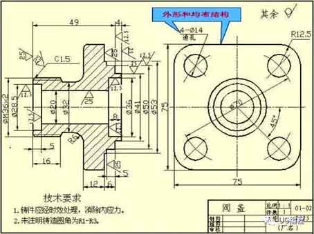
The basic shape of this kind of turned parts is a flat disc shape, generally including end caps, valve caps, gears and other parts. Their main structure is generally a revolving body, usually with various shapes of flanges, uniformly distributed circular holes and ribs and other partial structures. When selecting a view, generally select the cross-sectional view of the symmetry plane or the axis of rotation as the front view. At the same time, other appropriate views (such as left view, right view or top view) need to be added to express the shape and uniform structure of the part. As shown in the figure, a left view has been added to express a square flange with rounded corners and four evenly distributed through holes.
When marking the size of disc and cover parts, the axis passing through the shaft hole is usually selected as the radial dimension reference. The main dimension reference in the length direction often selects the important end face.
Fork and rack parts
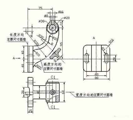
Such parts generally include forks, connecting rods, supports and other parts. Because their processing positions are changeable, when choosing the main view, the main consideration is the working position and shape characteristics. For the selection of other views, two or more basic views are often required, and appropriate local views, cross-sectional views, and other expression methods must be used to express the local structure of the part. The view selection and expression schemes shown in the part drawing of the footrest are concise and clear. For expressing the width of the bearing and ribs, the right view is not necessary, but for T-shaped ribs, a cross-sectional view is more appropriate.
When marking the dimensions of fork and rack parts, the installation base surface or the symmetry plane of the part is usually selected as the dimension reference. Refer to the figure for the dimensioning method.
Aluminum housing, cavity parts
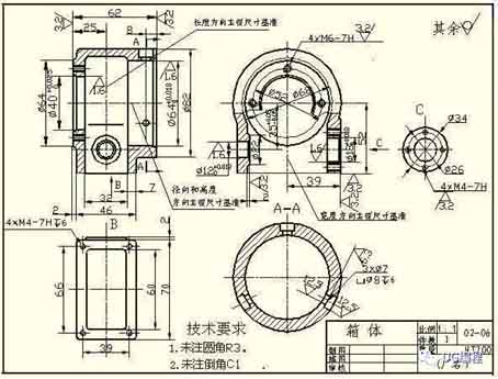
Generally speaking, the shape and structure of this type of cavity parts are more complex than the previous three types of parts, and the processing position changes more. Such parts generally include valve body, pump body, reducer box and other parts. When choosing the main view, the working position and shape characteristics are mainly considered. When selecting other views, appropriate sectional views, cross-sections, partial views and oblique views should be adopted according to the actual situation to clearly express the internal and external structures of the cavity parts.
In terms of dimensioning, the shaft line, important mounting surface, and contact surface (or processing surface) required by the design are usually selected. The symmetry plane (width, length) of some main structures of the box is used as the dimensional reference. For the positions on the box that need to be milled, the dimensions should be marked as far as possible to facilitate processing and inspection.
Shaft and sleeve parts
Such parts generally include shafts, bushings and other parts. When expressing views, as long as you draw a basic view and add appropriate cross-sectional views and dimensions, you can express its main shape features and local structure. In order to facilitate the viewing of the picture during processing, the axis is generally placed horizontally for projection, and it is best to choose the position where the axis is the lateral vertical line.
When marking the size of bushing parts, its axis is often used as the benchmark for radial dimensions. From this, the Ф14 and Ф11 shown in the figure (see A-A section), etc. are noted. In this way, the design requirements are unified with the process reference for CNC machining (when shaft parts are processed on a lathe, both ends of the shaft are supported by thimble against the center hole of the shaft). The length direction datum often chooses important end faces, contact faces (shaft shoulders), or machined faces.
When marking the dimensions of shafts and sleeve parts, its axis is often used as the benchmark for radial dimensions. From this, the Ф14 and Ф11 shown in the figure (see A-A section), etc. are noted. In this way, the design requirements and the process reference during processing (when the shaft parts are processed on the lathe, the center hole of the shaft is held by the thimble at both ends) is unified. The length direction datum often chooses important end faces, contact faces (shaft shoulders), or machined faces.
The surface roughness shown in the figure is the shoulder of the right shaft with Ra6.3. It is selected as the main size benchmark in the length direction, and sizes such as 13, 28, 1.5 and 26.5 are noted from this; Then take the right end of the shaft as the auxiliary base in the length direction to mark the total length of the shaft 96.
Disc and cover parts
The basic shape of this kind of turned parts is a flat disc shape, generally including end caps, valve caps, gears and other parts. Their main structure is generally a revolving body, usually with various shapes of flanges, uniformly distributed circular holes and ribs and other partial structures. When selecting a view, generally select the cross-sectional view of the symmetry plane or the axis of rotation as the front view. At the same time, other appropriate views (such as left view, right view or top view) need to be added to express the shape and uniform structure of the part. As shown in the figure, a left view has been added to express a square flange with rounded corners and four evenly distributed through holes.
When marking the size of disc and cover parts, the axis passing through the shaft hole is usually selected as the radial dimension reference. The main dimension reference in the length direction often selects the important end face.
Fork and rack parts
Such parts generally include forks, connecting rods, supports and other parts. Because their processing positions are changeable, when choosing the main view, the main consideration is the working position and shape characteristics. For the selection of other views, two or more basic views are often required, and appropriate local views, cross-sectional views, and other expression methods must be used to express the local structure of the part. The view selection and expression schemes shown in the part drawing of the footrest are concise and clear. For expressing the width of the bearing and ribs, the right view is not necessary, but for T-shaped ribs, a cross-sectional view is more appropriate.
When marking the dimensions of fork and rack parts, the installation base surface or the symmetry plane of the part is usually selected as the dimension reference. Refer to the figure for the dimensioning method.
Aluminum housing, cavity parts
Generally speaking, the shape and structure of this type of cavity parts are more complex than the previous three types of parts, and the processing position changes more. Such parts generally include valve body, pump body, reducer box and other parts. When choosing the main view, the working position and shape characteristics are mainly considered. When selecting other views, appropriate sectional views, cross-sections, partial views and oblique views should be adopted according to the actual situation to clearly express the internal and external structures of the cavity parts.
In terms of dimensioning, the shaft line, important mounting surface, and contact surface (or processing surface) required by the design are usually selected. The symmetry plane (width, length) of some main structures of the box is used as the dimensional reference. For the positions on the box that need to be milled, the dimensions should be marked as far as possible to facilitate processing and inspection.


