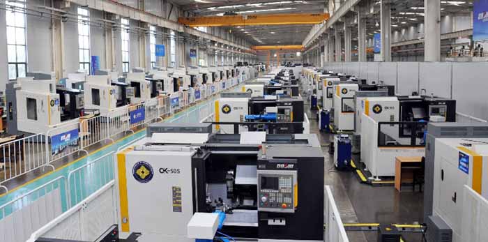
Milling Technology of Milling Machine
What is a milling machine and its milling technology settings?
Milling is a cutting manufacturing process for the production of workpieces with a geometrically defined shape. As with all machining processes, material is removed from a blank in the form of chips. Milling belongs to the group of cutting with geometrically defined cutting edges, since the geometry of the cutting edges on the milling tools is known. Rotary tool with several edges, which are called teeth, lips or carbide inserts. During milling, the material is removed by the milling tool rotating around its own axis at high speed, while either the tool follows the contour to be produced or the workpiece is moved accordingly. During milling, this feed movement takes place perpendicular or at an angle to the rotation axis of the tool - when drilling, however, it takes place in the direction of the rotation axis and when turning, the workpieces rotate around their own axis while the tool moves along the contour.With the increasing use of numerical control milling machines, the milling operations that can be carried out with this type of machine are increasing, and thus milling has become a multipurpose machining method. The development of the tools has also contributed to create new possibilities of milling in addition to considerably increasing the productivity, quality and accuracy of the operations carried out.
Milling is used in particular to produce flat surfaces. These include grooves or guides for moving machine parts. Before 1840, such shapes were mainly made by planing, after which it was quickly replaced by significantly faster milling. However, complex three-dimensional shapes such as turbine blades or dies can also be produced on modern milling machines. A large part of all gears is manufactured by hobbing, for which special hobs are required. Threads are also possible. Special processes are hard milling and high-speed milling.
Milling has some special features compared to other machining processes. In addition, it can only be carried out by machine, while there is almost always a manual variant. When milling, the individual cutting edges do not have constant contact with the workpiece. During one rotation, they penetrate the material, remove chips and detach themselves from the workpiece. This leads to a jerky, fluctuating course of the cutting force that acts on the tool. The chip thickness changes during the revolution and is not constant as in most processes. In addition, the angle between the cutting movement and the feed movement, the so-called feed direction angle, changes continuously during a tool revolution, which makes the calculation somewhat more complex. On the other hand, the cutting edges can cool down while they are not in contact with the workpiece and therefore do not heat up as much. In addition, the interrupted cut creates short comma-shaped chips that cannot get caught in the machine. Separate measures for chip breakage are therefore not required.
Definition of milling
Milling is often defined as a machining process in which the tool rotates. This is primarily to be understood as a demarcation from turning, another important manufacturing process in which the workpieces rotate around their own axis. In DIN 8589, milling is defined as follows:Milling is machining with a circular cutting movement assigned to the tool and any feed movement. The axis of rotation of the cutting movement maintains its position in relation to the tool regardless of the feed movement.

Milling Classification
Differentiation according to the direction of travelWhen milling, it is important to note how the direction of rotation of the tool is related to the direction of feed when cutting the cutting edge of the tool in the workpiece. Since the width of the incision should normally be no more than 2/3 of the tool diameter, the direction of travel is clear.
Up-cut milling
With up-cut milling, the cutting edge of the rotating tool moves in the area of engagement against the feed direction of the workpiece and forms a chip that thickens from the entry point to the exit point of the cutting edge (comma chip). Before the cutting edge enters the material, it slides on the work surface and solidifies the existing structure. This first creates a high level of friction and then the cutting edge has to penetrate the solidified material. As a result of the increasing chip thickness, the machine is loaded differently and tends to vibrate. This also causes the effort to increase slowly. When entering the cutting edge, it is low because little material still has to be removed, but then increases during the milling process and reaches its maximum value shortly before the cutting edge exits, before the comma chip is finally cut off.
The high pressure generated by the compaction during the milling process causes heavy wear on the flanks of the cutting edges, which reduces the service life. Due to this disadvantage, up-cut milling only makes economic sense if workpieces have hard (cast skin or scale) and wear-resistant edge zones (less hardening effect) or if the table drive is not without play. The surfaces milled in the opposite direction have a smooth but wavy structure due to the sliding action of the cutting edge.
For table drives with backlash, which usually only occurs with older or defective milling or boring mills, up-cut milling is recommended, because with this the milling cutter presses the driven workpiece table with evenly distributed load against the drive screw spindle. In this way, there is no backlash for the feed and undesired slide movements are excluded.
Down milling
With down-cut milling, the cutting edge of the rotating tool moves in the area of engagement in the direction of the vector of the workpiece feed direction. If the force builds up slowly with up-cut milling, with down-cut milling it is greatest as soon as the cutting edge enters, but then decreases continuously. The chip becomes thinner and thinner towards the cutting edge and is finally peeled off. which results in a smoother surface in relation to up-cut milling (here too, the chip is comma-shaped, but in this case a lot of material is removed at the beginning and little at the end).
Because of the lower cutting edge and flank wear, the feed rate can be increased by 50% compared to upstream milling with the same tool life.
Classification of the milling processes according to DIN 8589
The classification of milling, which is often cited in the specialist literature, is carried out, as with all other metal-cutting manufacturing processes, according to the shape produced into face, round, screw, hob, profile and shape milling. Face and profile milling is further subdivided according to the surface on the tool that creates the shape, milling into face, circumference and face circumference (profile).
Face milling
Face milling is used to produce flat surfaces. These include shoulders, sealing surfaces on flanges, motor or gear housings, guideways on machine tools, turret faces, basic tool holders and three-jaw chuck faces. Face milling is the most frequently used variant. In practice, the further subdivision is usually made according to the tools used in cylindrical milling, end milling, disc milling and others.
With circumferential face milling, the newly created surface is created with the cutting edges that are attached to the circumference of the milling cutter. The axis of the milling cutter is parallel to the surface created.
With face milling, the newly created surface is created with the cutting edges on the face. The cutter axis is perpendicular to the surface created. The main cutting work is still done by the main cutting edges on the circumference, only the surface is produced by the secondary cutting edges on the face, which is therefore of high quality. When face milling, the engagement width is usually significantly larger than the cutting depth. If the tool entering angle is also called shoulder milling. In general, it takes values between 45 ° and 75 °.
With face milling, both the cutting edges on the circumference and those on the face are used to create two new surfaces.
Round milling
With circular milling, circular cylindrical outer or inner surfaces are created. The feed movement, which is also circular, can be generated by the tool or the workpiece. Round milling bears the serial number.
Circumferential milling is characterized by the fact that the tool axis is parallel to the axis of rotation of the cylinder produced. This variant is also known as orbital milling or circular milling and is used to produce bores. It has the advantage over drilling that the diameter of the hole is not included in the tool. Different diameters can be produced with one milling tool. However, a complex CNC control is required for this.
With face milling, the tool axis is perpendicular to the axis of the generated cylinder. It is also known as turning-milling.
With face circumferential milling, the tool axis can be perpendicular or parallel to the generated cylinder. There are cutting edges on the circumference and on the face in engagement. This variant is also referred to as turning-milling.
Screw milling
Screw milling is used to produce screw-like shapes, including in particular threads and spindles or cylindrical worms.
A single-profile thread milling cutter is used for long thread screw milling. The feed corresponds to that of the thread pitch. The tool axis is slightly inclined in relation to the thread. It is similar to threading.
Short thread screw milling uses a multi-profile tool that is not inclined with respect to the thread. Here, too, the feed corresponds to that of the thread pitch. However, it only takes a little more than one workpiece revolution to produce the thread. It is similar to thread chasing.
Hobbing
Hob and milled toothing on a horizontal CNC hobbing machine
The hobbing with is used to generate hob surfaces. Above all, this includes gears on gears and racks. In principle, these can also be produced by gear planing and gear shaping or drop forging, but gear hobbing is the most important process. The hobs used have a profile that corresponds to that of the teeth to be produced. The rotation of the milling cutter, the feed and the rotation of the gear to be produced are coordinated with one another. The gears are then mostly finished by generating grinding.
Profile milling
Profile milling with uses profile milling cutters, which contain the shape to be produced as a negative, in order to produce profiles. These include T-slots, dovetail slots or the chip slots on large milling cutters. Circumferential grooves can also be created for workpieces that rotate around their own axis. Depending on the feed movement, round, straight or any shapes can be created. Numerous form elements on workpieces such as radii and bevels are standardized. This is why there are also corresponding standardized profile milling cutters.
Longitudinal profile milling is carried out with a straight feed movement.
Round profile milling, on the other hand, uses a circular feed movement.
The shape profile milling is carried out with any feed movement.
is profile milling with a milling chain.
Form milling
In form milling, tools are used that do not have the shape to be generated. Any three-dimensional shapes can be created by controlling the feed movement.
With free-form milling, the movement is controlled manually.
A template or masterpiece serves as a template for post-form milling. Their shape is scanned and passed on to the feed drives of the machine. The variant is also known as copy milling and has hardly been used since the introduction of CNC controls.
In kinematic form milling, gears are used to generate movement. These include cams or drum cams. It was used to manufacture large series of identical workpieces, but is rarely used today.
The NC form milling uses a numerical control (English: numerical control), today mostly in the form of a CNC control (computerized numerical control). In addition to the three movements in each axis direction, the tools can also be swiveled around two axes in order to create complex shapes. (The third axis is the rotation axis of the tool and therefore does not change the shape produced.) This process is used for the production of dies in mold making, for the production of casting molds (direct molding material milling) or for turbine blades.
Distinctions according to the materials to be processed
The cutting speed for metals covers a wide range depending on the type (brittle or tough). Machines such as those found in workshops or training facilities are used at cutting speeds of around 15–500 m / min. In series production or with milling-intensive workpieces, for example in Pelton turbines, all parameters are optimally coordinated due to the economic efficiency, and speeds of up to 10,000 m / min are possible. In most cases, cooling lubricants are used, but there is a clear tendency towards dry machining and minimum quantity lubrication. The share of cooling lubricant costs in the total costs of a milled workpiece is between 10 and 20%.The tools used also differ greatly in terms of cutting material and shape. In contrast to metal cutters, wood and plastic cutters always have a positive rake angle and larger chip spaces. In practice, single or double-edged end mills are used for machining plastics.