 English
 العربية
 中文(漢字)
 Čeština
 Dansk
Dansk Nederlands
 Suomi
Suomi Français
 Deutsch
 Italiano
 日本語
日本語 ಕನ್ನಡ
ಕನ್ನಡ 한국어
한국어 Português
 Русский
 Slovenčina
 Español
 Svenska
 Türkçe
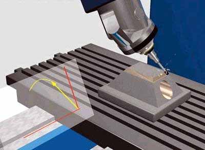
隨著多面、複雜曲面零件設計的增加, 5-軸加工在CNC加工中所佔比例將越來越大. 因為5軸數控加工增加了兩個旋轉自由度, 增加了CNC加工運動模擬計算和刀具干涉檢查的難度, 尤其是在加工形狀極為複雜的零件時. 所以, in order to ensure that 5-axis CNC machine tools perform high-efficiency and high-quality milling processing, the design of 5-axis machining tool path generation and interference checking software will become a major issue.
The feature projection method is suitable for 5-axis CNC machining tool interference processing, 那是, the machining surface is discretized into a series of surface feature points. 是否可以通過特徵點進入刀具表面的內部來判斷工具干擾的發生. 同時, the machining surface and the tool surface are projected onto a specific plane, and only the feature detection points in the curved surface area of the enveloping tool projection graph are checked for interference, 這提高了乾擾檢測的效率.
防止 5 軸銑削中的刀具干涉
1. Inspection method for tool interference
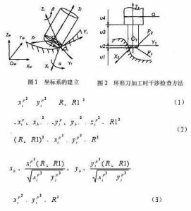
坐標系統和坐標轉換
如圖 1, the local coordinate system L of 5-axis circular cutter milling is represented as XL axis, YL軸和ZL軸. YL軸總是指向工具觸點的切割方向F (referred to as CC point) OL. The ZL axis points to the normal direction n of the surface, and the XL axis is determined by the right-hand rule of the YL axis and the ZL axis. 該工具通常以鉛角將XL軸從ZL軸旋轉到YL軸 (腳跟角) 一個, and rotates around the ZL axis one by one side slip angle b. 另外, 工具坐標系T (XT, 油田, ZT) 也可以在工具位置上定義 (簡稱CL點) OT. The YT axis points to the direction of the line connecting the CL point and the CC point. The ZT axis is the tool axis vector direction, and the XT axis is the direction determined by the right-hand rule of the YT axis and the ZT axis. The coordinate origin is located at the tool center point (即Cl點) OT. 為了簡化干擾檢查, 具有相對規則形狀的工具表面用作干擾檢查的參考. The machined surface is discretized to express the shape of the surface in the form of a set of characteristic points. 這些特徵點的原始數據在世界坐標系統W中表示, 因此,必須首先從世界坐標系轉換功能點數據 (OW-XW, 是, ZW) 到本地坐標系L (OL-XL, 是的, ZL) ). 然後將其從局部坐標系L轉換為工具坐標系T (ot-xt, 油田, ZT).
干擾檢查方法
如果選擇了工具和電源頭, 工具系統的大小 (工具和電力頭) 已知. Whether the tool system interferes with the machined surface can be determined by judging whether the characteristic point P enters the inside of the tool surface. 如圖 2, 這是工具系統和加工表面之間的位置關係. 在工具坐標系中, 讓特徵點p的坐標為pi (xpt, YPT, ZPT). 根據工具系統的不同組合部分, 特徵點P的坐標值ZPT分為 4 判斷部分. 詳細信息如下:
5-axis milling stroke setting formula
當特徵點P在U1的範圍內, 不會發生干擾.
當特徵點P在U2範圍內, 有兩種情況, and the torus is divided into two parts:
The small cylindrical part P1 and the circular ring part P2. 當特徵點涉及圓柱部分P1時, 發生工具干擾, 那是, it is satisfied
其中r表示工具的半徑, R1表示圓形工具環的半徑.
當特徵點涉及環零件P2時, 工具干擾也發生, 那是, it is satisfied
以風格
If the feature point P does not enter the parts P1 and P2, 不會發生工具干擾.
當特徵點P在U3的範圍內, 當特徵點P和ZT軸之間的距離小於刀具半徑, 發生工具干擾, 滿足
否則, 不會發生工具干擾.
When the characteristic point P is in the range of u4, 情況與 3, as long as the tool radius R in the formula (3) is replaced with the power head radius d/2 for judgment.