 English
 العربية
 中文(漢字)
 Čeština
 Dansk
Dansk Nederlands
 Suomi
Suomi Français
 Deutsch
 Italiano
 日本語
日本語 ಕನ್ನಡ
ಕನ್ನಡ 한국어
한국어 Português
 Русский
 Slovenčina
 Español
 Svenska
 Türkçe
在薄型零件的精加工中, 與粗加工的差別在於夾持力的影響, 精加工過程中必須充分考慮刀具和製程參數對零件內應力的影響. 以及銑削時切削力和銑削熱對零件結構的影響, 控制變形,避免效率提升所帶來的變形, 這會對零件的精度和表面品質造成損害.
銑削薄壁鋁合金零件刀具的選擇
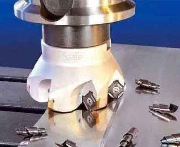
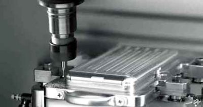
薄壁零件加工切削刀具的選擇
選擇更合理的工具可以直接提高生產效率. 鋁合金材料的銑削對刀具材料要求不高. 一般來說, 硬質合金銑刀就夠了, 塗層可以是無塗層或鑽石塗層. 粗加工時, 因為不需要考慮準確性和品質問題, 可以盡可能高效地去除金屬材料, 因此可以選擇一個大直徑工具以減少通行證數並縮短通行時間.
另外, 在粗糙的加工中, 嘗試選擇閉合工具而不是稀疏齒工具, 可以增加每革命的供稿, 並且切割速度可以以相同的速度提高. 在整理中, 除了考慮高效材料清除問題外, 在切割過程中,薄壁組件的力和變形控制問題也應完全考慮.
碳化物工具應用於完成高強度鋁合金薄壁零件. 工具的耙角不應太小, 否則切割變形和摩擦將增加, 耙子磨損會增加, 工具壽命將減少. 另外, 刀具尖端的弧形半徑的選擇應適當, 工具的牙齒不應太緻密,無法促進芯片排放. 進一步提高飼料率是有益的, 防止硬化層的耐磨層, 並延長工具的使用壽命.
設置銑削薄零件的工具路徑
選擇銑削薄零件的工具路徑
提高速度和效率的更有效的方法是優化工具路徑, 並確保高速切割期間工具路徑的方向性. 那是, 工具路徑盡可能簡單, 轉折點更少, 路徑盡可能平滑以減少方向快速變化; 閒置時間應減少, 並且應盡可能增加整個工件中切割時間的比例;
應該嘗試使用循環銑削, 通過不中斷切割過程和工具路徑. 減少工具的切割時間和切割時間, 並獲得穩定, 高效且高精度的加工過程.
小曲率半徑表面的工具路徑
小曲率半徑表面的工具路徑
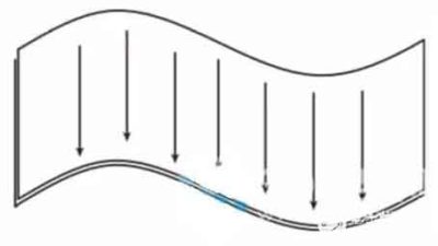
在整體結構部分的大而復雜的曲面的高速加工中, 當彎曲表面的曲率發生很大變化時, 最大曲率半徑的方向應用作最佳切割方向; 當彎曲表面的曲率變小時, 曲率半徑對切割方向的影響削弱. 最好選擇單個工具路徑的平均長度最長的切割方向.
水平工具路徑
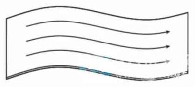
彎曲的刀具路徑,曲率較大
加工傾斜的飛機, 如果採用了水平切割, 每個細分市場的切割距離很短. 在銑削過程中, 主軸需要經常改變方向, 導致切割穩定性不佳. 而且因為銑削傾向於, 水平進料需要X或Y軸和Z軸的連鎖, 這不利於切割速度的提高.
選擇用於銑削薄零件的參數
銑削的水平水平工具路徑
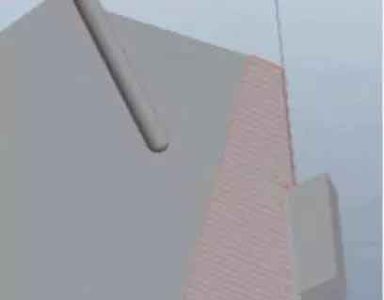
所以, 對於這種類型的斜角加工, 該工具路徑應盡可能平行於最長的斜角. 不僅工具路徑是最長的, 反轉時間的數量最少, 但是單個工具僅在X和Y平面中切割. Z軸向的運動在工件輪廓外安排, 即使在高速切割下也可以減少工具損壞.
銑削的傾斜平行工具路徑
選擇切割參數
粗加工時, 您通常可以選擇較大的進料率和適當的較大切割深度, 加上中等切割速度 “高功率” 高效切割, 可以實現高材料去除率, 從而大大提高了生產效率. 為了完成, 只有提高速度並增加牙齒的數量才是可行的. 增加每個牙齒的飼料可能會降低表面準確性, 導致殘餘應力和變形. 所以, “輕切和快速切割” 經常使用高切割速度和低飼料,通常用於確保生產效率的提高以及產品的準確性和表面質量.
切割參數可以通過切割有限元分析和切割測試來確定. 以最高主軸速度為24000R/min的龍門CNC加工中心為例. 通過分析第三波AdvantEdge軟件, 在薄壁面板的粗糙加工過程中, 如果您選擇φ25mm或φ32mm可填充的銑刀. 為了優化切割參數, 主軸速度應適當提高, 選擇範圍為12000 ~15000R/min; 每顆牙齒的進料和切割深度不應太大, 並且可選範圍分別為0.15mm/z和2~3mm.
銑削測試模擬數據的一部分
可以在從有限元分析獲得的參數的可選範圍內設計切割測試, 和切割效率, 表面粗糙度, 和加工的表面形貌用作評估標準, 最終選擇了最佳切割參數.
在鋁合金薄壁零件的高效加工策略下, 正確選擇上述銑削工具, 切割工具, 還需要銑削參數.