 English
 العربية
 中文(漢字)
 Čeština
 Dansk
Dansk Nederlands
 Suomi
Suomi Français
 Deutsch
 Italiano
 日本語
日本語 ಕನ್ನಡ
ಕನ್ನಡ 한국어
한국어 Português
 Русский
 Slovenčina
 Español
 Svenska
 Türkçe
葉輪是指裝有動葉片的輪盤. 葉輪的常見材料包括鑄鐵, 青銅, 不銹鋼, 錳青銅, 蒙乃爾合金, 鉻鎳鐵合金, 以及PPS塑膠等非金屬材料, 酚醛樹脂等. .
葉輪的加工要求:
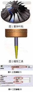
5-軸銑葉輪形狀
(1) 可以給予更大的能量頭;
(2) 氣體流經葉輪的損失小, 那是, 氣體流經葉輪的效率要高;
(3) 氣體從葉輪流出時參數合適, 使得氣體流經後續固定零件時的流動損失較小;
(4) 葉輪型式可拓寬整機性能曲線的穩定工況區與高效率區. 所以, 葉輪的銑削必須採用五軸聯動機床技術.
步 1: 銑削刀片輪廓
葉片仿形銑削採用錐形環刀 (直徑3毫米, 切割刃長度30mm). 見圖 2. 某葉輪單葉型加工所採用的方案-間廓銑削 2 曲線, 刀具的銑削範圍控制在兩條曲線之間. 切割類型的選擇 “取決於銑削量”, 透過切割量控制切割量,產生切割路徑, 如圖 3.
銑削模式為 “單路徑”, 單向加法的類型定義為 “順銑”. 以上兩個參數可以依照製程要求定義, 也應考慮葉輪的具體形狀, 如圖
產生葉輪葉片表面程式碼
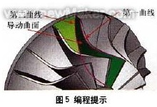
1. 定義幾何形狀
選擇葉輪葉片的外緣作為 “第一的” 曲線, 選擇葉輪葉片的內緣作為 “第二” 曲線, 並選擇兩片葉片之間的曲面作為 “導向面”. 以上 3 items為必選項,是產生的基本要求 “程式碼”.
這 “第一的” curve以空間輪廓限製曲面加工軌跡, 使軌跡在限制區域內進行處理 1;
這 “第二” curve以空間輪廓限製曲面加工軌跡, 使軌跡在限制區域內進行處理 2;
“導向面” 定義產品上要加工的表面對象, 如圖 5.
設定刀軸向量控制
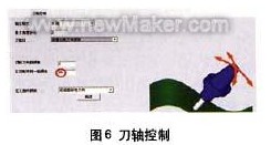
2. 定義刀軸控制
刀軸傾斜的方法定義為“根據銑削方向傾斜”. 考慮到需要使用刀具的側刃來加工, 此時需要合理控製刀軸向量. 採用根據銑削方向傾斜的方法, 刀具沿著曲面形狀的自然方向產生刀具路徑, 而這樣的刀具路徑加工的零件更加光滑. 這 “銑削方向的側傾角” 設定為 85°, 主要考慮切削刀具的錐角 (利用銑刀的側刃加工空間曲面,可以大幅提升曲面的精加工效率). 見圖 6.
注意上面的85°值, 這將使工具機連續旋轉. 觀察機器模擬. 這裡所說的旋轉是由於干涉檢查. 當我們使用80°或85°時, 在機器模擬中觀察刀具的變化和機器的變化, 並比較它們. 刀具錐角改為2.5°, 並重置設定以比較差異.
銑削葉輪干涉檢查
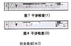
3. 定義干涉檢查
定義第一個乾涉檢查選項: 選擇引導面作為干涉檢查面, 系統會自動將新增的曲面加入為干涉檢查曲面. 這種情況的應用主要是為了解決加工後扭曲的導引面與刀具發生干涉的現象, 如圖 7.
定義第二個乾涉檢查選項: 再次選擇兩葉輪葉片之間的曲面作為第二干涉檢查面. 當工具發生干涉時, 它將 “沿刀具軸向退刀”. 檢查面是指刀具用於空間曲面加工時的干涉面, 如圖 8.
用於加工葉輪葉片的連續刀具路徑
4. 定義連續刀具路徑
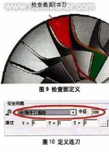
將連續刀具路徑類型定義為 “圓柱體平行於Z軸” 在安全範圍內. 由於它經過X0, Y0, 和 ZO 點且平行於 Z 軸, 刀具路徑之間的過渡將以半徑為100mm的圓柱體連接, 軸穿過 0 點並平行於 7 軸. 見圖 10. 選擇 “使用進給路徑宏命令” 在第一個提要中. 在最後一個回縮點, 選擇 “使用撤迴路徑宏”, 輸入巨集程式類型為 “反正切”, 並將圓弧掃描設定為 45°. 透過以上設定, 您可以進一步控製刀具路徑的進出, 如圖 11-14.
粗加工刀具進給路徑 + 精加工
前進、後退刀具路徑具有相同的宏命令設置, 所以結果是一樣的 (每層都相同) 必須在刀片加工刀具路徑中生產, 如圖 15.
步 2: 加工兩個葉輪葉片中間區域
銑削兩個葉輪葉片中間區域時, 球頭銑刀 (直徑3毫米) 用來, 曲面路徑為 “兩個曲面之間的仿形銑削”, 見圖 1. 切割方法是 “Z型銑削”, 切割順序為 “從內到外”, 如圖 2. 兩葉輪葉片的相對曲面定義為 “第一的” 曲面和 “第二” 曲面, 兩片葉片之間的曲面定義為 “驅動曲面”. 見圖 3.
1. 定義刀軸控制
刀具軸將 “透過曲線傾斜”, 見圖 4. 曲線逼近類型為 “接近點”, 和一個 “傾斜曲線” 建立在兩個葉片的外緣之間, 如圖 5. 建立曲線的方法是利用兩個葉輪的輔助曲面在頂部建立邊緣曲線. 曲面加工軌跡受空間輪廓限制, 使軌跡在限制區域內進行處理, 然後控製刀具的軌跡範圍.
2. 定義刀具路徑干涉檢查
選擇 “前線” 參與乾涉檢查的工具, 並檢查 “導向面” 和 “檢查表面”, 如圖 6. 檢查表面是否為兩葉輪葉片的內表面 (那是, 這 “第一的” 表面和 “第二” 上面提到的表面). 當然, 您必須再次選擇兩個曲面. 檢查‘引導面’表面時.
3. 定義連續刀具路徑
將第一條進給路徑定義為 “使用進給路徑宏指令”, 並將最後一個退刀點定義為 “使用縮迴路路徑巨集命令”, 如圖 7. 所有切片均使用刀路平滑連接 “混合樣條”, 如圖 8. 進給巨集程式採用 “垂直切向半徑”, 弧度掃描為 10°, 如圖 9. 這樣產生的進料和出料軌跡類似直線, 如圖l0所示.
第三步: 精加工過程中刀具軸的控制
定義空間曲線是控製刀軸的好方法, 它可以使您定義的刀具路徑非常平滑, 並且可以大大縮短計算時間. 然而, 空間曲線的定義需要非常豐富的實際加工經驗, 熟悉CAD指令,了解五軸航空銑相關功能. Cimatron系統會自動計算刀具的擺動方向,避免干擾和碰撞.
選擇引導面作為干涉檢查面, 並定義刀具路徑生成類型, 容差設定為 1.6. 邊際為 0.1 在這裡被保留, 這是最終根部去除過程中的處理餘裕, 如圖 1.
以免加工不當的情況發生, 我們使刀具路徑在切削/切削處延長10mm, 以免出現這種情況. 如圖所示 2. 將刀具直徑的百分比值設定為 10. 過程的結果如圖所示 3.
步 4: 以精加工為基礎的粗加工程序的刀具路徑控制
在整理的基礎上, 我們可以輕鬆地使用空白層來建立粗加工程序, 首先複製最後一個程序. 粗加工和銑削設定如圖所示 4.
在粗加工刀具路徑中, 分別定義層數和間距,然後定義加工刀具路徑的數量和間距. 這裡的間距是兩層之間的3D距離, 您也可以在這裡定義精加工刀具路徑.
定義曲面路徑中的引導曲面, 取消原先的導面, 並選擇剛剛建立的新旋轉曲面. 點選 “先進的” 選項並選擇 “在正面生成刀具路徑”, 如圖 5. 如果未選擇此選項, 刀具路徑將在整個葉輪葉片中生成. 此對話樞軸也可用於定義刀具路徑和表面之間的角度.
數位 5, 切割路徑與曲面的角度設置
計算程序段得到粗加工 + 精加工刀具路徑, 如圖 6.
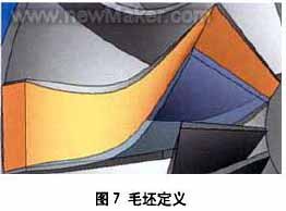
步 5: 添加毛坯以優化粗略刀具路徑
在每個程式段中新增空白以優化切割路徑. 建立 3 葉輪葉片之間的曲面, 並使用這些 3 用於定義毛坯的曲面. 刀片如圖 7.
調整刀片透明度,方便觀察毛坯. 選擇時, 我們可以看到會生成很多刀具路徑軌跡, 如圖 8.
除了零件之外, 有很多刀具路徑沒有參與切削. 現在透過簡單的設定來取消路徑中的這些空白. 複製最後一個程式並編輯它, 打開 “粗略定義” 選項, 並選擇您剛剛定義的粗糙表面, 如圖 9. 最後, 計算程式得到刀具路徑軌跡. 如圖 10.
如果您看到刀具路徑軌跡在空間中相連 (定義空白後), 這意味著您定義的毛坯在刀具路徑計算中起著一定的作用. 如果您對這種連接方式不滿意, 您可以變更對應的參數 “連續進給” 直到得到滿意的結果.