 English
 العربية
 中文(漢字)
 Čeština
 Dansk
Dansk Nederlands
 Suomi
Suomi Français
 Deutsch
 Italiano
 日本語
日本語 ಕನ್ನಡ
ಕನ್ನಡ 한국어
한국어 Português
 Русский
 Slovenčina
 Español
 Svenska
 Türkçe
無聊的, 銑削是一種內徑切削工藝,其中使用刀具擴大孔或其他圓形輪廓. 其應用範圍一般從半粗加工到精加工, 所用刀具通常為單刃鏜刀 (稱為鏜桿工具).
鏜削是鏜削和銑削的一種.
用反向鏜刀加工反向鏜孔的方法稱為反向鏜孔加工.
在CNC機床上, 我們經常使用非標準工具 (偏心鏜刀, 旋轉刀片, 特殊反鏜工具) 使用 CNC 加工程序進行反向鏜孔加工.
用旋轉單刃鏜刀將工件上的預製孔擴大到一定尺寸, 從而達到切削加工所需的精度和表面粗糙度. 鏜孔一般在鏜床上進行, 加工中心和組合工具機. 主要用於加工圓柱孔 (看圖片), 螺紋孔, 盒子等工件上的孔和端面的凹槽, 支架和機器底座; 使用特殊附件時, 還可加工零件的內外球面、錐孔. 金屬構件的鏜孔精度一般可達IT9~7, 表面粗糙度Ra2.5~0.16微米.
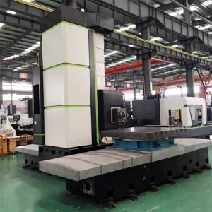
臥式銑床和鏜床 CNC 加工服務
無聊的時候, 工件安裝在工具機工作台或工具機夾具上, 鏜刀夾緊在鏜桿上 (它還可以與鏜桿集成), 由主軸帶動旋轉. 使用鏜模時, 鏜桿與主軸浮動連接, 而加工精度取決於鏜模的精度; 不使用鏜模時, 鏜桿與主軸剛性連接, 而加工精度取決於工具機的精度. 由於無聊桿的懸垂距離很大, 它很容易產生振動, 而且選定的切割量不應很大. 無聊的過程分為粗糙的無聊, 半精細的無聊和無聊的. 使用高速鋼切割機以鑽孔時的切割速度通常為普通鋼 20-50 M/我; 使用碳化物尖端時的切割速度, 粗糙的無聊可以到達 40-60 M/我, 而且無聊的能力超過 150 M/我.
對於需要高精度和表面粗糙度的精確鑽孔, 鑽石無聊的機器通常使用, 和超胸材料的工具,例如碳水化合物, 鑽石和立方硼氮化物用於. 選擇一個很小的飼料 (0.02-0.08 mm/rev) 和切割深度 (0.05-0.1 毫米), 比普通無聊的切割速度高. 精確鑽孔的加工精度可以達到IT7〜6, 表面粗糙度為RA0.63〜0.08微米. 精確無聊之前, 預製的孔經受了粗糙的鑽孔, 半精細的無聊和無聊的, 留下薄而均勻的加工津貼,以使精度無聊.
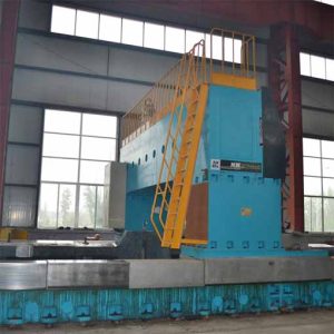
Gantry CNC銑床和無聊的機器的加工服務
常用的無聊工具
無聊工具的類型
根據切割邊緣的數量, 它可以分為單調的無聊工具, 雙刃無聊的工具和多邊鑽孔工具; 根據其加工表面, 它可以通過無聊工具分為, 盲孔工具, 踩踏孔鑽孔工具和端面無聊工具; 根據其結構, 它可以分為整體類型, 組裝類型和可調類型. 數位 1 顯示單邊鑽孔工具和多邊鑽工具的結構.
單邊鑽工具
單邊鑽頭頭的結構類似於轉動工具的結構. 切刀頭安裝在工具架中, 並且根據正在處理的孔的直徑,用手動操作固定切割機頭的位置. 工具頭垂直於無聊的桿的軸,可以通過孔孔孔, 而且傾斜的安裝可以帶有盲孔.
單邊鑽孔工具具有簡單的結構, 可以糾正原始孔軸偏差和較小的位置偏差, 並且具有廣泛的適應性, 可用於粗糙, 半固定或完成. 然而, 通過手動調節切割機的懸垂長度,可以保證無聊的孔的大小, 這很麻煩. 另外, 只有一個主要尖端參與工作, 所以生產效率低, 多用於單件小批量生產.
雙刃鏜刀
雙刃鏜刀有兩個對稱的切割刃, 切削時徑向力可以互相抵消. 工件孔徑的直徑和精度由鏜刀的徑向尺寸保證.
CNC鏜床
鏜削刀具有三個基本要素: 可轉位刀片, 柄和鏜座. 鏜刀柄用於固定刀柄, 保持長度通常約為 4 乘以刀柄直徑. 鑲裝刀柄從鏜座伸出的長度稱為懸伸量 (鏜刀不受支撐的部分). 懸垂確定鑽孔的最大深度,是無聊工具的最重要維度. 過度的懸垂會導緻小腿的嚴重撓度, 引起chat不休, 這會損害工件的表面質量,並可能導致過早插入失敗. 這些將降低處理效率.
對於大多數加工應用, 用戶應選擇具有最高靜態和動態剛度的無聊工具. 靜態剛度反映了鑽孔工具承受切割力引起的撓度的能力, 動態剛度反映了無聊工具抑制振動的能力.
本文的第一部分主要分析鑽孔工具的靜態剛度. 本文資料來自作者對鏜刀偏轉的研究. 鏜刀的偏轉取決於刀柄材料的機械性質, 刀柄直徑和切削條件.
切削力
作用在鏜刀上的切削力可用旋轉測功機測量. 測量的力包括切向力, 進給力和徑向力. 與其他兩股勢力相比, 切向力的大小最大.
切向力垂直於刀片前刀面作用,並將鏜刀向下推. 值得注意的是,切向力作用在刀片尖端附近,而不是作用在刀柄的中心軸線上. 切向力偏離中心線產生力臂 (柄中心線到受力點的距離), 這會產生一個力矩,導致鏜孔刀具相對於其中心線扭轉.
進給力是第二大力,平行於刀桿中心線作用, 因此不會引起鏜刀的偏轉. 徑向力垂直於刀柄中心線作用,並將鏜刀推離正在加工的表面.
所以, 只有切向力和徑向力會使鏜刀偏轉. 已經使用了幾十年的經驗演算法是: 進給力和徑向力約為 25% 和 50% 切向力的, 分別. 今天, 然而, 這種比例關係不被認為是 “最優演算法” 因為各個切削力之間的關係取決於特定的工件材料及其硬度, 切削條件, 和鼻半徑.
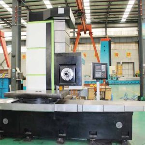
龍門銑鏜床CNC加工服務
鏜刀偏轉
鏜刀類似於一端固定的懸臂梁 (鏜座夾緊件) 另一端不受支撐 (工具列懸垂), 因此可以透過懸臂梁撓度計算公式計算鏜刀的撓度:
y=(F×L3)/(3埃×我)
在公式: F是合力; L 是懸垂 (單元: 英吋); E是彈性模量 (那是, 刀柄材料的楊氏模量) (單元: 磅/平方英寸, 磅每平方英寸);
I 為刀架截面的轉動慣量 (單元: 英吋4).
計算無聊條段慣性矩的公式為:
i =(π×d4)/64
在哪裡: D是無聊條的外徑 (單元: 英吋).
無聊工具的撓度計算示例:
處理條件:
工件材質: AISI 1045 碳素鋼, 硬度HB250;
切割深度: 0.1“”,
餵養: 0.008 英寸/修訂;
小腿直徑: 1“”,
刀片的彈性模量: E = 30×106psi,
小腿的懸垂: 4″.
(1) 切向力的計算
ft = 396000×切割深度×進率×功率常數= 396000×0.1×0.008×0.99 = 313.6磅
(2) 徑向力的計算
FR = 0.308×ft = 0.308×313.6 = 96.6磅
(3) 計算產量
F = 328.1磅
(4) 計算本節的慣性矩:
i =(π×d4)/64= 0.0491英寸4
(5) 計算無聊工具的撓度
y=(F×L3)/(3埃×我)= 0.0048“
分析了鏜刀撓度和截面轉動慣量的計算公式. 鑽孔時應遵循下列原則:
(1) 鏜刀的懸伸量應盡量小. 因為隨著懸垂增加, 撓度也增加. 例如, 當懸垂增加一個因子時 1.25, 撓度將增加近一倍 2 而刀柄外徑和切削參數保持不變.
(2) 鏜桿直徑應盡量大. 因為當柄部直徑增加時, 其截面的轉動慣量也會增加, 且偏轉量會減少. 例如, 當柄部直徑增加一倍時 1.25, 撓度將減少近乎 2.5 具有相同的懸伸和切削參數.
(3) 當懸垂時, 刀桿外徑和切削參數保持不變, 使用高彈性模量材料的鏜桿可以減少撓度.