CNC freze parçalarının parametreleri nasıl ayarlanır?
Freze işleminde dikkate alınması gereken temel parametreler aşağıdakiler:
Makine türünün seçimi, Çoğunlukla ve aracı sabitlemek için aksesuarlar ve sistemler.
Frezeleme türünün seçimi: frontal, Anlaşmada veya eksenel n'opozit.
Kesme parametrelerinin seçimi: kesme hızı (VC), Araç Xiru Hızı (N), kesme hızı (VA), derinlik (P), kesme genişliği (AC), vesaire.)
İşleme sektöründe öğütme prosedürlerinin isimleri konusunda oybirliği yok. Eksenel frezeleme periferik frezeleme de denir, silindirik öğütme, veya sarmal öğütme. İki tür eksenel öğütme, isimlerle de bilinir:
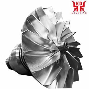
CNC Freze Parçalarının Parametrelerini Ayarlayın
Eşleşecek şekilde frezeleme: frezeleme ters alçaktır, veya aşağı akım frezeleme.
Frezeleme pozisyonu: frezeleme kenara karşıdır, veya normal frezeleme.
Frezelemede buna uygun olarak, alet xira parçanın ilerleyişinde aynı hissi veriyor. Bu tip frezeleme aynı zamanda kontra-düşük frezeleme olarak da bilinir çünkü, değirmenin xiru'su yatay olduğunda, kesme kuvvetinin dikey bileşeni pakete doğru yönlendirilir. Frezeleme pozisyonunda, aynı zamanda kenara karşı frezeleme olarak da bilinir, tam tersi oluyor, bu, takım parçanın en iyi noktasına ters yönde gidecektir ve kesme kuvvetinin dikey bileşeni kenara doğru yönlendirilecektir.
İşlenmiş yüzeyde kaliteli elde etmek için, Tutarlı frezeleme, Dexar makinesinden her zaman en çok önerilen öğütme yöntemidir, Araç ve Araçlar.
Muhalefete karşı frezelemede, Araç ilerledikçe dövmenin kalınlığı ve kesme basıncı artar, Bu nedenle makine için daha az güç gereklidir. Evet ise, Bu yöntemin dezavantajları var. Makinede titreşimler ve işlemenin daha kötü bir yüzey kalitesi üretti. Parçayı tutmaya dikkat etmek gerekir, çünkü aletin göbekleri onu demirlemeden dışarı itme eğiliminde olacaktır..
Uyumlu frezelemede, Kesicinin dişleri kuyruk parçasını maksimum kalınlıkta kesmeye başlar , Freze ve karşıtlıktan daha büyük bir kesme çabası gerektiren kutup. Kesici parçadan çıkarıldığında, Dövmenin kalınlığı daha azdır ve bu nedenle çalışma basıncı daha azdır, böylece işlenmiş yüzeyin daha iyi bir yüzeyini üretiyor. Bu öğütme yönteminin daha güçlü ve sert makineleri vardır. Bu öğütme, parçanın desteğini tercih etti çünkü altına açma eğilimindedir.
Kesme kenarlarının kesimi eksenel yönde ve radyal yönde ilerletmesine izin veren araçlar kullanırken, Çoğu durumda,, Kesici kesilirken, Radyal yönde daha iyi hareketler öncelik olarak yapılmalıdır.
Bunun nedeni, kesme kenarlarının xeometrisinin, Çoğu durumda, Kesim radyal bir yönde ilerledikçe daha katlanmış olacak şekilde tasarlanmıştır. Bunu akılda tutarak, Bu araçlarla derinleşen hareketler tercihen bir boşlukta yapılmalıdır., Diğer araçlarla ilk sondaj veya kuyu delme yoluna yol açar, matkaplar veya trepanning kronları vasıtasıyla. Evet ise, Kesicileri şekillendiren yuvarlak ekler kullandıklarında, Meyora'nın yönü kayıtsız.
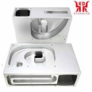
CNC kesme hızı
Kesme hızı
Ana makale: Kesme hızı
Bunu, kesicinin çevre hızında veya öğütme kullanan diğer aletin doğrusal hızında kesme hızı olarak tanımlayın. Kesme hızı, dakikada metre cinsinden ifade edilir (M / min), İşlemeye başlamadan önce seçilmelidir ve değeri birçok faktöre bağlıdır, özellikle kullanılan kesici kalitesi ve türü. kullanmak, İşlenecek malzemenin sertliği ve işlenebilirliği ve en iyi hız kullanılan. Makinenin ana sınırlamaları hız aralığıdır, Motorların gücü ve parçanın ve aletin sabitlenmesinin sertliği.
Freze kesicinin her bir kesim kenarı aralıklı olarak çalışırken, Aracın her devriminin sadece bir kısmını kesmek, Kesme kenarları, asla ulaşamayacaklarından daha düşük sıcaklıklara sahiptir ve, Ne olursa olsun, Hızları Kullanın. daha yaşlı kesim. Evet ise, Freze kesicinin işi asla aralık olarak kabul edilemez, çünkü çalışma aşamasında her zaman bir son teknoloji olduğu için.
Kesme hızının belirlenmesinden, Aracın sahip olacağı dakikadaki devrimler aşağıdaki formüle göre belirlenebilir:
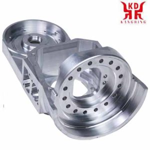
Aracı Dönüş Hızını Ayarla
VC'nin kesme hızı olduğu yer, n, aletin dönüş hızıdır, ve DC aracın çapıdır.
Kesme hızı, aracın ömrünü belirleyen ana faktördür. Yüksek kesme hızı, işlemenin daha kısa sürede gerçekleştirilmesini sağlar, ancak aletin aşınmasını hızlandırır. Araç ve işleme kılavuzları üreticileri, aletin belirli bir yararlı ömrü veya süresi için araçların hızlı kesme hızı hakkında değerli veriler sağlar., duruma göre 15 dakika. Durumlarda, Aracın farklı bir süresi için kesme hızını ayarlamak ve üretkenliği optimize etmek istenir, hangisine, Kesme hızının değerleri bir düzeltme faktörü ile çarpılır. Bu düzeltme faktörü ile rahibe ve llinial kesim aracı nooperasyonunun süresi arasındaki ilişki.
Aşırı kesme hızı, alet kesme kenarının çok hızlı aşınmasına yol açabilir, İşleme toleransı kaybı ile kesme kenarının plastik deformasyonu ve, genel olarak konuşursak, Kötü işleme kalitesi. Diğer taraftan, Çok düşük olan bir kesme hızı, araca katkı oluşumuna yol açabilir, Tahliye zorlukları ve işleme süresinde bir artış, düşük bir üretkenliğe ve yüksek bir işleme maliyetine dönüşür.
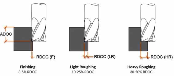
CNC kesme veya çalıştırma derinliğini ayarlayın
Takım dönüş hızı
Milin dönme hızı, Davezu'nun dakikada devrimler halinde ifade edilmesi (devir/dakika). Geleneksel freze makinelerinde sınırlı bir hız aralığı vardır, Ana motorun çalışma hızına ve makinenin şanzımanındaki hız sayısına bağlı olarak. Sayısal kontrol freze makinelerinde, Bu hız, çeşitli hızlarda herhangi bir hızı seçebilen bir geri bildirim sistemi ile kontrol edilir., maksimum hıza kadar.
Aracın dönme hızı, kesme hızı ile doğru orantılıdır ve aletin çapı ile ters orantılıdır.
Öğütmenin en iyi hızı, parça ve araç arasındaki göreceli hızdır, Bu, kesimin ilerlediği kuyruk hızıdır. Kesme alet ucunun daha iyi ve yarıçapı, öğütme yüzeyinin pürüzlülüğünün bağlı olduğu en önemli iki faktördür..
Her kesici, aletin devrimi başına en iyi hızları etkili bir şekilde kesebilir, devrim başına en iyi şekilde adlandırıldı (fn). Bu aralık temelde kesicinin diş sayısına bağlıdır, her dişin boyutu ve kesim derinliği, Parçanın malzeme türüne ve kesme plakasının kalitesi ve türüne ek olarak. Bu hız aralığı deneysel olarak belirlenir ve ek üreticilerimize eklenir’ kataloglar. Ek olarak, Bu hız, parçanın ve takım ataşmanlarının sertliği ve makinenin motorunun gücü ile sınırlıdır.. MM'nin maksimum kalınlığı, bir öğütme aracı için en önemli sınırlama göstergesidir. Aletlerin son teknesi, belirli bir değere sahip olmak için test edilir ve maksimum kaba.
Devrim başına iyileşme (fn) diş sayısı başına diş başına iyileşmenin ürünüdür (zıpla) aletin.
İyileştirme hızı, aletin dönme hızının devrim başına iyileştirmenin ürünüdür.
Aracın dönme hızı kuyruğu gibi, Geleneksel freze makinelerinde en iyi hız, bir kutu değişiklikte bulunan bir dizi hız seçer, Sayısal kontrol freze kesicilerinin en iyisinden maksimuma kadar herhangi bir hızla çalışabileceği. Makinenin maksimum hızı.
Gelişme hızı, oluşum için belirleyicidir, güç tüketimi, yüzey pürüzlülüğü, mekanik stresler, kesme alanındaki sıcaklık ve verimlilik. Yüksek bir iyileştirme hızı, iyi bir kontrole ve işlenmiş yüzey birimi başına aletin daha uzun bir süresine yol açar, aynı zamanda yüksek yüzey pürüzlülüğüne ve aletin frayatos veya aşırı sıcaklıklar tarafından bozulma riskine neden olur. Evet ise, Daha yavaş bir hız, döngüler ve daha yüksek işleme süresi oluşturabilen daha uzun formaxes oluşumuna yol açar, Bu, yüzey birimi başına alet süresinin daha kısa olduğu ve üretimin daha pahalı olduğu anlamına gelir..
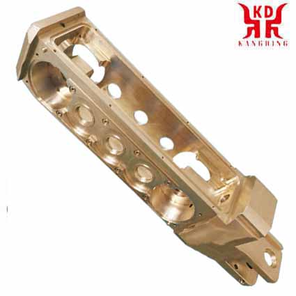
Hızlı işleme
Kesme veya koşu derinliği
Geçişin kesilmesi veya derinliği derinliği (P) ve tabakanın derinliği, aletin tek bir geçişinde parçanın yüzeyinden köşeli. Davezu milimetre içinde ifade edildi (mm). Kesme genişliği (S), mm ile ifade edildi, ve parçanın parçasının genişliği. Bu parametreler, dövme bölümünün hesaplanmasının ve sonuç olarak işlenmeyi gerçekleştirebilmesi için gerekli kesme kuvvetine sahip olduğu etkisi nedeniyle dikkate alınmalıdır..
Geçişin derinliği bir priori olarak kurulur ve esas olarak işlenecek malzemenin büyümesine bağlıdır., elde edilecek boyutsal hassasiyet derecesi, Makinenin gücü ve en iyi seçilenlere göre ilişki ve kesme plakasının parametreleri. büyüklüğü gibi, ucun yarıçapı ve profili. Dövme işleme yaparken, Daha yüksek geçiş derinliklerine ve daha hızlı hızlara sahip işlenmeye izin veren daha uzun bir kesme kenarına sahip kenarları kullanın. Evet ise, Operasyonlar için d’Acabáu, Daha küçük kesim derinliği alın.
Etkili kesme uzunluğu (.), Kesilen uzunluğun uzunluğu ile doğrudan ilişkili maksimum değerdir, kesimin derinliğine bağlı (P) ve konum açısı.
Çalılık ve bölüm
Çilek Diş başına en iyi arasındaki ilişki (fz) ve kesimin derinliği (P) bölümünü oluşturur. Bölüm ayrıca gerçekleştirilen öğütme türü ile de ilgilidir., Bölüm, deliğin kalınlığına eşittir..
Bölümün ve kalınlığın kontrolü, işleme işleminin belirlenmesinde önemli faktörlerdir. Başlangıç anının kalınlığı ne kadar küçük olursa, Filu yükü daha az olacak ve bu, Mesmu'ya zarar vermeden diş başına daha yüksek iyileşme hızlarının uygulanmasına izin verecektir., kenarlar alanındaki daha küçük açılar nedeniyle kesme derinliğini azaltmak zorunda. Bölümü kontrol etme gücü, esas olarak makinenin gücü gibi faktörlere bağlıdır., parçanın fiksasyonu veya sıkıştırma sistemi, Takım manşonunun bölümü ve eklerin sıkıştırılması ve aletin xeometrisi. onları mesmes. Bölümdeki artış ve kalınlık, diğer değişkenlerin yanı sıra, Malzemenin giderilmesinin gerçekleştirilmesi için gereken güçte bir artış anlamına gelir.
İşleme süresi
Bir öğütme makinesinin işleme süresini hesaplamak için, Frezeleme kesicinin işlendiği kısımdan yaklaşımı ve çıkışının uzunluğunu dikkate almak gerekir.. Stil uzunluğu, değirmencinin türüne bağlıdır. Bu arada, Yaklaşımın uzunluğu, aletin metal çapı ile çakışır; Groove frezeleme farklıdır ve oluğun derinliğine ve kesicinin çapına bağlıdır; ve iç veya dış kontur frezelemesinde, işleme uzunlukları kesicinin çapına ve konturlu yüzeyin xeometrisine bağlı.
Özel kesme kuvveti
Kesme kuvveti, aletteki ve bir parçadaki fray frayatos ve deformasyonlardan kaçınmak ve işleme tayini yapmak için gerekli gücü hesaplayabilmek için dikkate alınması gereken bir parametredir.. Bu parametre öğütme hızına bağlıdır, kesme hızı, Malzemenin işlenebilirliği, Malzemenin sertliği, Aracın özellikleri ve dövmenin ortalama kalınlığı. Tüm bu faktörler, spesifik kesme kuvveti adı verilen bir katsayısına dahil edilmiştir (KC), N'de ifade edilen / mm².
Hızlı işleme
Hızlı işleme kavramı, Yüksek hızlı işleme de denir (Mav), modern makinelerle üretilen hangilerine bakın, Güçlü ve sağlam kafalara sahip sayısal kontrol araçları 30,000 devir/dakika, ve çok büyük iş, yumuşak malzemelerin işlenmesi söz konusu olduğunda ve birçok Baleráu de Forgaxa ile kalıp üretimi veya havacılık endüstrisinin büyük bileşenleri ile ilişkili olacak şekilde çok büyük iş. Yüksek işlenmiş metaller ve alaşımlar, hızlı işleme konseptinde en popüler olanlardır. Karmaşık şekilli parçaların hızlı işlenmesi için, Yüksek hızda belirli yörüngeleri üreten CAM sistemlerini kullanın, Dövme ve bitirme.
 English
 العربية
 中文(漢字)
 Čeština
 Dansk
Dansk Nederlands
 Suomi
Suomi Français
 Deutsch
 Italiano
 日本語
日本語 ಕನ್ನಡ
ಕನ್ನಡ 한국어
한국어 Português
 Русский
 Slovenčina
 Español
 Svenska
 Türkçe

