 English
 العربية
 中文(漢字)
 Čeština
 Dansk
Dansk Nederlands
 Suomi
Suomi Français
 Deutsch
 Italiano
 日本語
日本語 ಕನ್ನಡ
ಕನ್ನಡ 한국어
한국어 Português
 Русский
 Slovenčina
 Español
 Svenska
 Türkçe
Pervane, hareketli kanatlarla donatılmış bir tekerlek diskini ifade eder. Pervaneler için yaygın olarak kullanılan malzemeler arasında dökme demir bulunur, bronz, paslanmaz çelik, manganez bronz, Monel, INCONEL, ve PPS plastik gibi metalik olmayan malzemeler, fenolik reçine ve benzeri. .
Pervane için işleme gereksinimleri:
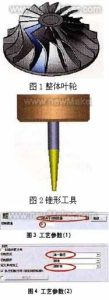
5-eksen frezeleme pervanesi şekli
(1) Daha büyük bir enerji yükü verebilir;
(2) Pervaneden akan gazın kaybı küçük olmalıdır, yani, Pervaneden geçen gazın verimi yüksek olmalıdır;
(3) Gaz pervaneden dışarı aktığında parametreler uygundur, böylece gaz sonraki sabit bileşenlerden akarken akış kaybı küçüktür;
(4) Pervane tipi, tüm makinenin performans eğrisinin istikrarlı çalışma koşulu alanını ve yüksek verimlilik alanını genişletebilir. Öyleyse, Pervanenin frezelenmesinde 5 eksenli bağlantı makinesi teknolojisi benimsenmelidir.
Adım 1: Bıçak profilinin frezelenmesi
Bıçak profili frezelemede konik bir halka kesici kullanılır (çap 3mm, kesme kenarı uzunluğu 30mm). Şekile bakın 2. Belirli bir pervanenin tek bıçak tipi profil frezeleme ile işlenmesi için benimsenen çözüm 2 eğriler, ve takımın frezeleme aralığı iki eğri arasında kontrol edilir. Kesim tipi seçimi “öğütme miktarına bağlıdır”, kesme yolunu oluşturmak için kesme miktarı kesme miktarı tarafından kontrol edilir, Şekilde gösterildiği gibi 3.
Frezeleme modu “tek yol”, ve tek yönlü toplamanın türü şu şekilde tanımlanır: “tırmanma frezeleme”. The above two parameters can be defined according to the process requirements, and the specific shape of the impeller should also be considered, Şekilde gösterildiği gibi
Generate impeller blade surface code
1. Define the geometry
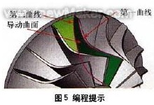
Select the outer edge of the impeller blade as the “first” curve, select the inner edge of the impeller blade as the “ikinci” curve, and select the curved surface between the two blades as the “guide surface”. The above 3 items are required options and are the basic requirements for generating “code”.
The “first” curve restricts the curved surface processing trajectory with the contour of the space, so that the trajectory is processed in the restricted area 1;
The “ikinci” curve restricts the curved surface processing trajectory with the contour of the space, so that the trajectory is processed in the restricted area 2;
“Guiding surface” defines the surface object to be processed on the product, Şekilde gösterildiği gibi 5.
Set tool axis vector control
2. Define tool axis control
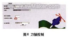
The method of tool axis tilt is defined as “tilt according to the milling direction”. Considering the need to use the side edge of the tool for processing, it is necessary to control the tool axis vector reasonably at this time. Using the method of tilting according to the milling direction, the tool generates a tool path along the natural direction of the curved surface shape, and the parts processed by such a tool path are smoother. The “side inclination angle in the milling direction” is set to 85°, which mainly takes into account the taper angle of the cutting tool (using the side edge of the milling cutter to process the curved surface of the space can greatly improve the finishing efficiency of the curved surface). Şekile bakın 6.
Pay attention to the above value of 85°, takım tezgahının sürekli dönmesini sağlayacak. Makine simülasyonunu gözlemleyin. Burada bahsedilen rotasyon girişim kontrolünden kaynaklanmaktadır. 80° veya 85° kullandığımızda, makine simülasyonunda takım değişimini ve makinenin değişimini gözlemleyin, ve bunları karşılaştırın. Takım konik açısı 2,5° olarak değiştirildi, ve farkları karşılaştırmak için ayarlar sıfırlanır.
Freze çarkının girişim denetimi
3. Parazit kontrolünü tanımlayın
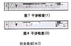
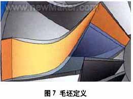
İlk engelleme kontrolü seçeneğini tanımlayın: Girişim kontrol yüzeyi olarak ön yüzeyi seçin, ve sistem eklenen yüzeyi otomatik olarak girişim kontrol yüzeyi olarak ekleyecektir. Bu durumun uygulanması esas olarak bükülmüş kılavuz yüzeyinin işlendikten sonra takıma müdahale etmesi olgusunu çözmektir., Şekilde gösterildiği gibi 7.
İkinci engelleme kontrolü seçeneğini tanımlayın: İkinci engelleme kontrol yüzeyi olarak iki pervane kanadı arasındaki kavisli yüzeyi tekrar seçin. Alet müdahale ettiğinde, o olacak “takım ekseni yönü boyunca geri çekme”. Kontrol yüzeyi, uzay kavisli yüzey işleme için kullanıldığında aletin girişim yüzeyini ifade eder, Şekilde gösterildiği gibi 8.
Pervane kanatlarının işlenmesi için sürekli takım yolu
4. Sürekli takım yolunu tanımlayın
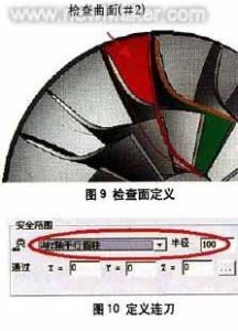
Sürekli takım yolu tipini şu şekilde tanımlayın: “Z eksenine paralel silindir” güvenlik aralığında. X0'dan geçtiği için, Y0, ve ZO noktalarıdır ve Z eksenine paraleldir, takım yolları arasındaki geçiş, 100 mm yarıçaplı bir silindire bağlanacaktır, içinden geçen eksen 0 nokta ve paralel 7 eksen. Şekile bakın 10. Seçme “Besleme yolu makro komutunu kullan” ilk beslemede. In the last retraction point, select “Use retraction path macro”, enter the macro program type as “arc tangent”, and set the arc sweep to 45°. Through the above settings, you can further control the in and out of the tool path, Şekilde gösterildiği gibi 11-14.
Tool feed path for roughing + Bitiricilik
The forward and backward tool paths have the same macro command settings, so the same results (the same for each layer) must be produced in the blade processing tool path, Şekilde gösterildiği gibi 15.
Adım 2: Processing the middle area of the blades of the two impellers
When milling the middle area of the blades of the two impellers, a ball-end cutter (çap 3mm) is used, and the curved surface path is “profiling milling between two curved surfaces”, Şekil'e bakın 1. The cutting method is “Z-type milling”, and the cutting sequence is “from inside to outside”, Şekilde gösterildiği gibi 2. The relative curved surfaces of the blades of the two impellers are defined as the “first” curved surface and the “ikinci” curved surface, and the curved surface between the two blades is defined as the “driving curved surface”. Şekile bakın 3.
1. Define tool axis control
The tool axis will “tilt through the curve”, Şekil'e bakın 4. The curve approach type is “approach point”, and an “inclined curve” is established between the outer edges of the two blades, Şekilde gösterildiği gibi 5. The method of establishing the curve is to use the auxiliary surface of the two impellers to establish an edge curve at the top. The curved surface processing trajectory is restricted by the contour of the space, so that the trajectory is processed in the restricted area, and then the trajectory range of the tool is controlled.
2. Define tool path interference check
Select the “cutting edge” of the tool to participate in the interference check, and also check the “guide surface” Ve “check surface”, Şekilde gösterildiği gibi 6. Check that the surfaces are the inner surfaces of the two impeller blades (yani, the “first” surface and “ikinci” surface mentioned above). Elbette, you must select the two surfaces again. When checking the ‘guide surface’ surface.
3. Sürekli takım yolunu tanımlayın
Define the first feed path as “use feed path macro command”, and define the last tool retraction point as “use retract path macro command”, Şekilde gösterildiği gibi 7. All slices are connected smoothly with the knife path using “mixed splines”, Şekilde gösterildiği gibi 8. The feed macro program adopts “vertical tangential radius”, and the arc sweep is 10º, Şekilde gösterildiği gibi 9. The trajectory of the infeed and outfeed generated in this way is similar to a straight line, as shown in Figure l0.
The third step: the control of the tool axis during the finishing process
Defining the space curve is a good way to control the tool axis, it can make the tool path you define is very smooth, and can greatly shorten the calculation time. Fakat, the definition of the space curve requires a very rich experience in actual machining, familiarity with CAD instructions and an understanding of the related functions of 5-axis aviation milling. The Cimatron system will automatically calculate the swing direction of the tool to avoid interference and collision.
Girişim kontrol yüzeyi olarak ön yüzeyi seçin, and define the tool path generation type, and the tolerance is set to 1.6. A margin of 0.1 is reserved here, which is the margin for processing during the final root removal, Şekilde gösterildiği gibi 1.
In order to avoid the occurrence of improper processing, we make the tool path extend 10mm at the cutting/cutting place, so as to avoid this kind of situation. as shown in picture 2. Set the percentage value of the tool diameter to 10. Bu prosedürün sonucu Şekilde gösterilmektedir. 3.
Adım 4: Finisaj bazında kaba işleme programına dayalı takım yolu kontrolü
Bitirme temelinde, kaba işleme programını oluşturmak için boş katmanı kolayca kullanabiliriz, ilk önce son programı kopyalayın. Kaba işleme ve frezeleme ayarları Şekilde gösterilmektedir 4.
Kaba işleme takım yolunda, sırasıyla katman sayısı ve aralık tanımlanır ve ardından işleme aracı yolunun sayısı ve aralığı tanımlanır. Buradaki boşluk, iki katman arasındaki 3 boyutlu mesafedir, burada ayrıca son işlem takım yolunu da tanımlayabilirsiniz.
Yüzey yolundaki kılavuz yüzeyi tanımlayın, orijinal kılavuz yüzeyini iptal edin, ve az önce oluşturulan yeni döner yüzeyi seçin. Tıkla “Gelişmiş” seçeneğini belirleyin ve seçin “Ön tarafta takım yolu oluşturun”, Şekilde gösterildiği gibi 5. Bu seçenek seçili değilse, takım yolu pervane kanadının tamamında oluşturulacaktır. Bu diyalog pivotu aynı zamanda takım yolu ile yüzey arasındaki açıyı tanımlamak için de kullanılabilir.
Figür 5, kesme yolu ile kavisli yüzey arasındaki açı ayarı
Kaba işlemeyi elde etmek için program segmentini hesaplayın + bitirme aracı yolu, Şekilde gösterildiği gibi 6.
Adım 5: Kaba takım yolunu optimize etmek için boşluklar ekleyin
Kesim yolunu optimize etmek için her program bölümüne boşluklar ekleyin. Kurmak 3 pervane kanatları arasındaki kavisli yüzeyler, ve bunları kullan 3 boşluğu tanımlamak için yüzeyler. Bıçak şekilde gösterilmiştir 7.
Bıçağın şeffaflığını, boşluğu gözlemlemeyi kolaylaştıracak şekilde ayarlayın. Seçerken, çok sayıda takım yolu yörüngesinin üretileceğini görebiliriz, Şekilde gösterildiği gibi 8.
Parçalara ek olarak, kesmeye katılmamış birçok takım yolu var. Now through simple settings to cancel the path of these blanks. Copy the last program and edit it, open the “Rough Definition” option, and select the rough surface you just defined, Şekilde gösterildiği gibi 9. Nihayet, calculate the program to get the tool path trajectory. Şekilde gösterildiği gibi 10.
If you see the tool path trajectory connected in space (after the blank is defined), it means that the blank you defined plays a certain role in the tool path calculation. If you are not satisfied with this connection method, you can change the corresponding parameters in “Continuous feed” until you get a satisfactory result.