 English
 العربية
 中文(漢字)
 Čeština
 Dansk
Dansk Nederlands
 Suomi
Suomi Français
 Deutsch
 Italiano
 日本語
日本語 ಕನ್ನಡ
ಕನ್ನಡ 한국어
한국어 Português
 Русский
 Slovenčina
 Español
 Svenska
 Türkçe
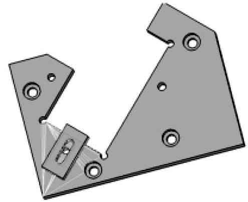
Üç boyutlu tasarım yazılımının geliştirilmesi, düşük maliyet için koşullar sağlar, kısa süre, ve konumlandırma armatürlerinin tasarımı. Ve doğrulama için CNC işleme parçalarını simüle edebilir. Figür 1 YZ ve ZX düzlemlerine 45° açıyla tipik bir metal parçayı gösterir:
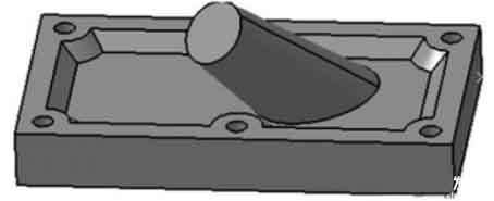
Özel yapıya sahip CNC işleme parçaları
figür 1 Parça Planı CNC işleme planını seçmek
Özel mekansal yapıya sahip bu tür parçalar genellikle 2 CNC işleme yöntemleri türleri:
① Takım takımının performansını geliştirin, yani, Orijinal 2.5 eksenli veya 3 eksenli CNC takım takımını 5 eksenler;
② Uygun bir konumlandırma fikstürü tasarlayın ve işleme için mevcut ekipmanı kullanın.
İşleme maliyetini göz önünde bulundurarak, İkinci seçenek açıkça daha ideal bir seçimdir. Aşağıdakiler, bu bölüm için bir konumlandırma fikstürü tasarlamaktır, ve sağlam modelleme yapmak için CATIA yazılımını kullanın, toplantı, parazit tespiti, ve fikstürün her bir bileşeninin doğruluk analizi. Tasarımın fizibilitesini ve doğruluğunu kontrol etmek için sanal işleme için tasarlanan fikstürü CNC işleme modülüne aktarın.
Konumlandırma fikstürünün tasarımı ve 3D modellemesi
İşlenmiş parçaların özelliklerini göz önünde bulundurarak, İşlemin doğruluğunu sağlamak, ve fikstürün uygulama kapsamını iyileştirmek için, Konumlandırma fikstürü, modüler bir kombine fikstür olarak tasarlanmıştır, Şekilde gösterildiği gibi 2. Fikstür esas olarak 4 parçalar: konumlandırma braketi, konumlandırma plakası, Kılavuz modülü ve konumlandırma kelepçesi. Konumlandırma braketi tüm fikstürün temel taşıdır, konumlandırmanın eğimini doğrudan belirler, ve üzerine başka parçalar da kuruldu.
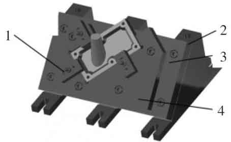
3D konumlandırma fikstürünün katı modeli
Figür 2 Üç boyutlu katı konumlandırma fikstürü modeli
1. Konumlandırma klibi
2. Konumlandırma braketi
3. Konumlandırma plakası
4. Rehberlik modülü
Konumlandırma plakası, kılavuz modülünü konumlandırma braketine takmak için kullanılır, ve işlenecek iş parçasının taban yüzeyinin boyutu ve şekli 45° eğimle değiştiğinde, yalnızca kılavuz modülün yapısının ve boyutunun değiştirilmesi gerekir. Sabitleme için konumlandırma plakası üzerinde uygun bir konumun seçilmesi, konumlandırma kelepçesinin daha geniş bir aralıkta kullanılabilmesini sağlar. Kılavuz modülün ve konumlandırma kelepçesinin tasarımı, işlenen parçanın yapısına ve şekline göre yapılmalıdır., işlenecek parçanın dış yüzeyiyle eşleşecek şekilde, Konumlandırma kelepçesinin kurulumunu kolaylaştırmak için yükseklik aynı olmalıdır. Konumlandırma kelepçesi genellikle üç noktalı konumlandırmayla tasarlanmış ve monte edilmiştir., ve sınırlamayı gerçekleştirmek için konumlandırma plakasıyla işbirliği yapar. 6 işlenecek parçaların serbestlik dereceleri.
Konumlandırma fikstürünün statik girişim denetimi
Tasarlanan fikstürün bileşenlerinin işlenebilmesini ve monte edilebilmesini sağlamak amacıyla, ve konumlandırma işlevini gerçekleştirebilir, fikstür üzerinde girişim tespiti yapılmalıdır.
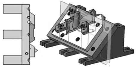
Statik girişim analizi, fikstür birimleri arasındaki girişimi ve fikstür ile iş parçası arasındaki girişimi içerir.. Her fikstür birkaç üniteden oluşur, ve tamamlama, konumlandırma ve sıkıştırmayı içerir. Sınırlı alan ve her birimin karmaşık yapısı nedeniyle, ve armatürün tasarımı genellikle katman katman tasarlanır, alanın kenarını kontrol etmek zordur ve müdahale edilmesi kolaydır. Ek olarak, iş parçasının şekli karmaşıktır, ve fikstür ünitesinin yeri veya yapısı nedeniyle iş parçası doğru şekilde monte edilmeyebilir..
Fikstürün dinamik çarpışma tespiti
Figür 3 Statik girişim tespitinin şematik diyagramı
Altında “Dmuspaceanaliz” CATIA'daki Modül, fikstürde statik parazit analizi yapın, ve çarpışma tespitini kullanın “Checkclash” ve bölüm aracı “Kesit tanımlama” fikstürü tespit etmek için.
Dinamik parazit analizi
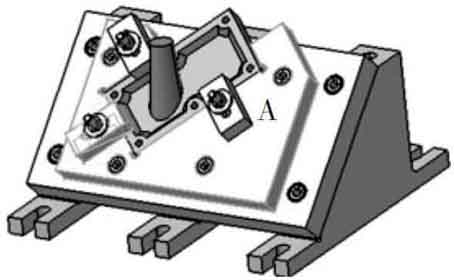
Kullanın “Dumffitting” monte edilen ürünleri incelemek için CATIA tarafından sağlanan modül. Montaj sırasında parçaların aktarım yolunu kaydedebilir, Parçaları monte ederken hareketli parçaların gerektirdiği dinamik alanı analiz edin, ve parçalar arasındaki paraziti tespit edin. İlk geçiş “montaj tasarımı” ki “Dumffitting” modül, ve her montaj yolunu fikstür düzenine göre verin, her bir bileşenin transfer mesafesi bilgilerini içerir. Amaç, parazit meydana geldiğinde spesifik parazit pozisyonunu ve derinliğini elde edebilmektir., Ardından düzenli montaj simülasyonunu kurun, Ve sonunda aç “çarpışma” analiz. Analiz sonucu şekilde gösterilmiştir 4.
Fikstürün statik girişim tespitinin şematik diyagramı
Figür 4 Dinamik çarpışma tespiti
Şekilde gösterilen A alanı 4 parazitin meydana geldiği yer, ve özel ekranı şekilde gösterilmiştir 5. Konumlandırma kelepçesi ile kılavuz modülü arasında parazit meydana gelir. Müdahale bilgilerinin analizi yoluyla, Montaj işlemi sırasında konumlandırma klipsinin kılavuz modülünün montaj yoluyla çarpıştığı sonucuna varılmıştır.. Müdahale için görünür, Fikstürde aşağıdaki değişiklikleri yapın: Konumlandırma noktasını ve sıkıştırma noktasını değiştirme öncülünde, Mekansal konumu veya ünitedeki diğer parçaların bazı boyut parametrelerini değiştirin.
Fikstürün algılama parazit alanı
Figür 5, parazitin meydana geldiği alan
CNC simülasyon işlemesi
Kullanın “işleme” CATIA tarafından, iş parçasını işlerken aracın fikstürle çarpışıp kalmadığını kontrol etmek için iş parçasında CNC işleme yapmak için sağlanan modül, CNC işlemenin fizibilitesini doğrulamak için. Çarpışmanın sezgisel olarak gerçekleşip gerçekleşmediğini gözlemleyebilmek için, Bu makale, taslak silindirin dış konturunu iş parçasında uzamsal eğimle işlemeyi seçmektedir.. Birinci, monte edilen armatürü “Yüzey işleme” altında “İşleme” gerçekleştirilecek modül “Kontur odaklı” (Konturla Tahrikli Sonlandırma) işlenmiş parçanın dış yüzeyinde;
Ardından açılan iletişim kutusunda işlenecek parça olarak işleme alanını seçin, ve uygun takım yolu parametrelerini seçin, sürüş kılavuz çizgisinin seçimi dahil, uygun takım parametreleri ve takım çıkış rotası;
Nihayet, Takım yolu çizgisini oluşturmak için CNC simülasyon işlemi gerçekleştirilir, Şekilde gösterildiği gibi 6.
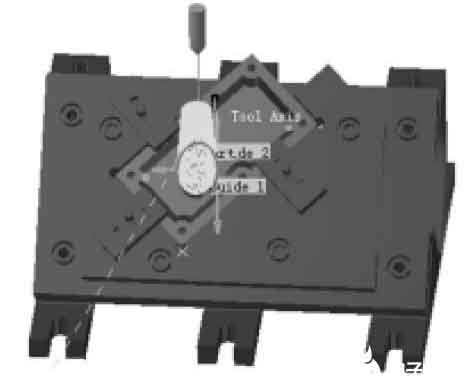
CNC işleme parçaları tarafından oluşturulan takım yolu çizgileri
Figür 6, oluşturulan takım yolu çizgisi
Fikstürün toplam konumlandırma hatası:
(Burada δK= iş parçasının işlem boyutu toleransı)
Yukarıdaki durumlar, CATIA'nın üç boyutlu sanal tasarım yeteneklerinin kullanımı yoluyla maliyetleri etkili bir şekilde azaltabilir ve tasarım ve üretim döngüsünü kısaltabilir., konumlandırma armatürlerinin tasarımı ve işlevsel testleri; Tüm tasarım kompozisyonunda, bilgisayar, CNC takım tezgahlarında tasarımdan montaja ve simülasyon işlemeye kadar olan süreci tamamlar, Statik ve dinamik girişim analizi dahil. Bu, geleneksel tasarım yöntemleriyle eşsizdir, ve aynı zamanda modern demirbaş endüstrisinin gelişmesinde de kaçınılmaz bir eğilimdir..