 English
 العربية
 中文(漢字)
 Čeština
 Dansk
Dansk Nederlands
 Suomi
Suomi Français
 Deutsch
 Italiano
 日本語
日本語 ಕನ್ನಡ
ಕನ್ನಡ 한국어
한국어 Português
 Русский
 Slovenčina
 Español
 Svenska
 Türkçe
CNC இயந்திர கருவிகளுக்கான கருவிகளை அளவீடு செய்வது எந்திரத்தில் ஒரு முக்கியமான திறமையாகும். கருவி அமைப்பின் துல்லியம் பகுதியின் இயந்திர துல்லியத்தை தீர்மானிக்கிறது, மற்றும் அளவுத்திருத்த கருவியின் செயல்திறன் நேரடியாக பகுதியின் எந்திர செயல்திறனை பாதிக்கிறது. இயந்திர கருவி செயலாக்க செயல்பாடுகளுக்கு கருவி அமைப்பு மிகவும் முக்கியமானது.
After the CNC lathe is turned on, the zero return (reference point) operation must be performed. Its purpose is to establish a unified reference for position measurement, control, and display of the CNC lathe, அது, the tool returns to the origin of the machine tool. இயந்திரக் கருவியின் தோற்றம் பொதுவாக கருவியின் அதிகபட்ச நேர்மறை பக்கவாதத்தில் இருக்கும், மற்றும் அதன் நிலை இயந்திர கருவி நிலை சென்சார் மூலம் தீர்மானிக்கப்படுகிறது. இயந்திர கருவி பூஜ்ஜியத்திற்கு திரும்பிய பிறகு, கருவியின் நிலைக்கு இடையே உள்ள தூரம் (கருவி முனை) மற்றும் இயந்திர தோற்றம் சரி செய்யப்பட்டது. எனவே, கருவி அளவுத்திருத்தம் மற்றும் செயலாக்கத்தை எளிதாக்கும் வகையில், இயந்திரம் பூஜ்ஜியமாக திரும்பிய பிறகு கருவி முனையின் நிலை இயந்திரத்தின் தோற்றமாக கருதப்படலாம்.
CNC எந்திரத்திற்கான கருவி அளவுத்திருத்த முறை
கருவியை அளவீடு செய்வது என்பது CNC இயந்திர கருவியின் இயந்திர ஒருங்கிணைப்பு அமைப்பில் பணிப்பகுதி ஒருங்கிணைப்பு அமைப்பை நிறுவுவதற்கான செயல்முறையாகும்., மற்றும் ஒர்க்பீஸ் ஒருங்கிணைப்பு அமைப்பின் தோற்றம் நிரலாக்க தோற்றத்துடன் ஒத்துப்போகிறது. Measure the distance between the tool tip programming point in the machine tool coordinate system and the machining origin in the X and Z directions by trial cutting or non-contact methods, and set the value to the machine parameters. Through the program call, the coordinate system of the workpiece is established. The absolute coordinate value of the base point in the program is based on the origin of the established workpiece coordinate system, and the contour of the part is processed.
There are many ways to calibrate the knife on the CNC lathe, and the trial cutting method is commonly used in the work. The following introduces FANUC-0I CNC lathe commonly used calibration tool method.
1. Measure and input tool offset method
1) Trial cut the outer circle of the workpiece with the selected tool, மற்றும் கருவியை X திசையில் சீரமைக்கவும். கைமுறை செயல்பாட்டு முறையில், வெளிப்புற வட்டத்தை வெட்ட முயற்சிக்கவும், X திசையை மாற்றாமல் வைத்திருங்கள், மற்றும் கருவி Z அச்சில் வெளியேறுகிறது. வெட்டப்பட்ட வெளிப்புற வட்டத்தின் விட்டம் மதிப்பு α ஐ அளவிட, வெர்னியர் காலிபரைப் பயன்படுத்தவும், மற்றும் கிளிக் செய்யவும் “ஆஃப்செட்செட்டிங்” வடிவ இழப்பீட்டு அளவுரு அமைப்பு இடைமுகத்தை உள்ளிட பொத்தான். கருவி இழப்பீட்டின் X நிலைக்கு கர்சரை நகர்த்தவும், Xα ஐ உள்ளிடவும், மற்றும் மென்மையான விசையை கிளிக் செய்யவும் [அளவிடவும்]. இயந்திரக் கருவி ஒருங்கிணைப்பு அமைப்பில் X திசையில் தற்போதைய கருவி முனையின் ஆயங்களை எண்ணியல் கட்டுப்பாட்டு அமைப்பு தானாகவே கணக்கிடுகிறது., மற்றும் X திசையானது கருவியின் அளவுத்திருத்தத்தை நிறைவு செய்கிறது.
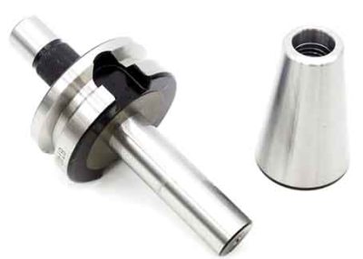
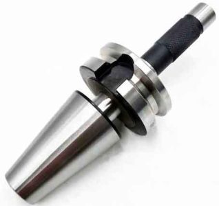
இயந்திர கருவி அளவுத்திருத்தம்
2) இறுதி முகத்தை வெட்டி, Z திசையில் கருவியை அளவீடு செய்ய தேர்ந்தெடுக்கப்பட்ட கருவியைப் பயன்படுத்தவும். கைமுறை செயல்பாட்டு முறையில், கருவி பணிப்பகுதியின் இறுதி முகத்தை மையமாக வெட்டுகிறது. பிறகு Z திசை அசையாமல் இருக்கும், மற்றும் கருவி X திசையில் வெளியேறுகிறது. வடிவ இழப்பீட்டு அளவுரு அமைப்பு இடைமுகத்தை உள்ளிடவும், கருவி இழப்பீடு Z ஒருங்கிணைப்பின் தொடர்புடைய நிலைக்கு கர்சரை நகர்த்தவும், Z0 ஐ உள்ளிடவும், அழுத்தவும் [அளவிடவும்] மென்மையான விசை, தொடர்புடைய கருவி ஆஃப்செட் தானாகவே உள்ளீடு செய்யப்படுகிறது, மற்றும் கருவி அமைப்பு முடிந்தது. இந்த முறையானது பணியிடத்தின் வலது முனையின் மையத்தில் எந்திர தோற்றத்தை அமைப்பதாகும், இது பொதுவான தண்டு பகுதிகளுக்கான பொதுவான முறையாகும். அது இடது-வலது சமச்சீர் பகுதியாக இருந்தால், இயந்திர தோற்றம் பணிப்பகுதியின் சமச்சீர் மையத்தில் அமைக்கப்பட வேண்டும், பின்னர் Zβ ஐ உள்ளிடவும், β என்பது பகுதியின் அச்சு நீளத்தின் பாதி.
பின்னர் கருவியின் வடிவியல் அளவு மற்றும் நிறுவல் நிலைக்கு ஏற்ப கருவியின் மூக்கு ஆர்க் ஆரம் R மற்றும் கருவி நிலை எண் T ஆகியவற்றை உள்ளிடவும்., உதாரணத்திற்கு:
எண். 1 கருவி, கருவி முனை ஆர்க்கின் ஆரம் R=0.8mm, கர்சரை எண்ணுடன் தொடர்புடைய நிலைக்கு நகர்த்தவும். 1 கீழே உள்ள கருவி ஆர், முக்கிய 0.8, T இன் தொடர்புடைய நிலையில் கருவி நிலை எண்ணை உள்ளிடவும், மற்றும் அழுத்தவும் “உள்ளீடு” உள்ளீடு செய்ய, பின்னர் அதை செயலாக்க பயன்படுத்த முடியும்.
2. இசட்-திசை அளவுத்திருத்தக் கத்தி, பணிப்பகுதியைத் திருப்பிய பிறகு
பணிப்பகுதி திரும்பிய பிறகு, எந்திரம் எந்திரத்திற்குப் பிறகு பகுதியின் ஒட்டுமொத்த நீளத்தை உறுதி செய்ய வேண்டும். எனவே, கத்தி இரண்டு முறை அளவீடு செய்யப்பட வேண்டும். X திசையானது முந்தைய கருவி அமைப்பு முறையைப் போலவே உள்ளது. Z-திசை கருவி அமைப்பின் படிகள் பின்வருமாறு:
பணிப்பகுதியின் இறுதி முகத்தை மையமாக வெட்டுங்கள், keep the Z direction still, press the X forward button, and the tool exits. Measure the total length of the workpiece blank in Z direction as Z1, the required total length of the workpiece is Z, and the length difference is ∆=Z1-Z. Before executing the program, you must first set the O point as the machining origin (படம் பார்க்கவும் 1), and enter the shape compensation parameter setting interface. Move the cursor to the Z coordinate position, enter Z∆, (∆ is the Z coordinate value of the current position of the tool tip in the newly created workpiece coordinates), அழுத்தவும் [அளவிடவும்] மென்மையான விசை, and the corresponding tool offset is automatically input.
3. G92 sets the workpiece coordinate system
1) Use an external turning tool to first try turning the external circle. After measuring the diameter of the outer circle, the tool is withdrawn in the positive direction of the Z axis, and the spindle stops. Note down the absolute coordinate value X1 of the tool in the machine tool coordinate system at this time, and measure the outer circle diameter D at the same time.
2) Cut the end face to the center, X does not move, and exit along the Z direction. Write down the absolute coordinate value Z1 of the tool in the machine tool coordinate system at this time;
3) Select the starting point. The starting point should be selected outside the workpiece. If the starting point is set at 50mm in the X direction and 50mm in the Z direction from the center of the right end face. Then the position of the starting point in the machine coordinate system X = X1-D+100.0 (diameter programming), Z=Z1+50.0;
4) புள்ளியை அடைய கருவியை சரிசெய்யவும். G92 ஆல் அமைக்கப்பட்ட பணிப்பகுதி ஒருங்கிணைப்பு அமைப்புடன் நிரலை இயக்குவதற்கு முன், கருவி மேல்-புள்ளி நிலைக்கு சரிசெய்யப்பட வேண்டும். கீழே உள்ள வழிமுறைகள்:
முதலில் கருவியை கைமுறை நிலையில் தொடக்கப் புள்ளிக்கு அருகில் உள்ள நிலைக்கு நகர்த்தவும், பின்னர் துல்லியமான நிலையை அடைய ஹேண்ட்வீல் மூலம் உருப்பெருக்கத்தை சரிசெய்யவும்;
5) இந்த நேரத்தில், நிரலின் தொடக்க புள்ளியாக இருக்க வேண்டும்: G92 X100.0 Z50.0
விளக்கம்:
(1) இந்த வழிமுறையை செயல்படுத்துவதற்கு முன் கருவி அளவீடு செய்யப்பட வேண்டும், மற்றும் கருவி முனையை இயந்திர கருவியை சரிசெய்வதன் மூலம் நிரல் தேவைப்படும் தொடக்க புள்ளி நிலையில் வைக்க வேண்டும்;
(2) G92 கட்டளையை இயக்குவது இயந்திரக் கருவியின் எந்த இயக்கத்தையும் ஏற்படுத்தாது. கணினி பழைய ஆய மதிப்பை புதிய ஆய மதிப்புடன் மாற்றட்டும், thereby establishing a new coordinate system.
When using the trial cutting method to verify the tool, the error of the verification tool mainly comes from the measurement error after the trial cutting of the workpiece and the error caused by the visual inspection during the operation. The main measures to reduce the tool setting error are: The attitude must be rigorous, the operation must be careful, and the reading must be accurate; செயலாக்கும் போது, consider the influence of the machine tool’s repeated positioning accuracy on the tool setting accuracy and the influence of the installation height of the tool location point on the tool setting accuracy; After tool setting, the tool compensation value should be corrected according to the error between the actual size of the part processed by the tool and the programmed size.
Numerical control lathes have a variety of control systems. The tool calibration methods include manual calibration, calibration of external calibrator of the machine tool, and automatic calibration. Manual tool setting adopts the mode of “trial cutting-measurement-adjustment”, which is simple and economical, takes a long time in the machine tool, and has a large error. Using the calibrator for tool setting can automatically calculate the difference between the length of each knife and the standard knife, and store it in the system. When processing other parts, only the standard knife is needed, which greatly saves work assistance time. கூடுதலாக, the use of a tool setting instrument for tool setting can eliminate errors during measurement and greatly improve the accuracy of tool setting. Automatic tool setting is realized by the tool tip detection system. The tool tip approaches the touch sensor at a set speed. When the tip of the tool touches the sensor and sends a signal, the CNC system immediately records the coordinate value at that moment and automatically corrects the tool compensation value. Although the principle of inputting parameters of external tool setting instrument and automatic tool setting is similar to that of manual tool setting, the principle and method of measurement are different, the degree of automation is high, and the work efficiency is improved.
ஒவ்வொரு கருவி அளவுத்திருத்த முறைக்கும் அதன் சொந்த நன்மைகள் மற்றும் தீமைகள் உள்ளன, மற்றும் ஆபரேட்டர்கள் தங்கள் உண்மையான தேவைகளுக்கு ஏற்ப அவற்றை நெகிழ்வாகப் பயன்படுத்தலாம். இந்த வழியில், முழு கருவி அமைப்பு வேலை எளிது, மற்றும் செயலாக்க தரத்தை உறுதி செய்ய முடியும், மற்றும் துணை நேரத்தை பெரிதும் சேமிக்க முடியும், மற்றும் உற்பத்தி திறனை திறம்பட மேம்படுத்த முடியும்.