Boring, milling is an inner diameter cutting process in which a tool is used to enlarge a hole or other circular contour. Its applications generally range from semi-roughing to finishing, and the tools used are usually single-edged boring tools (called boring bar tools).
Boring is a type of boring and milling.
The method of processing the reverse boring hole with the reverse boring tool is called reverse boring processing.
On CNC machine tools, we often use non-standard tools (eccentric boring tools, rotating inserts, special reverse boring tools) to perform reverse boring processing using CNC machining programs.
The prefabricated hole on the workpiece is enlarged to a certain size with a rotating single-edge boring tool, so that it can achieve the required precision and surface roughness cutting. Boring is generally carried out on boring machines, machining centers and combination machines. It is mainly used for machining cylindrical holes (see picture), threaded holes, grooves in holes and end faces on workpieces such as boxes, brackets and machine bases; When special accessories are used, the inner and outer spherical surfaces and taper holes of the parts can also be processed. The boring accuracy of metal components can generally reach IT9~7, and the surface roughness is Ra2.5~0.16 microns.

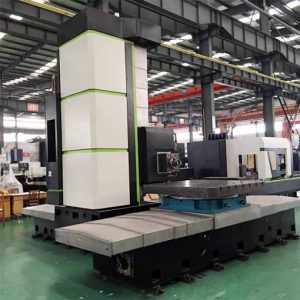
CNC machining services for horizontal milling and boring machines
When boring, the workpiece is installed on the machine tool table or machine tool fixture, and the boring tool is clamped on the boring bar (it can also be integrated with the boring bar), which is driven by the spindle to rotate. When the boring die is used, the boring bar and the main shaft are floatingly connected, and the machining accuracy depends on the accuracy of the boring die; When the boring die is not used, the boring bar and the spindle are rigidly connected, and the machining accuracy depends on the accuracy of the machine tool. Due to the large overhang distance of the boring bar, it is easy to generate vibration, and the selected cutting amount should not be large. The boring process is divided into rough boring, semi-fine boring and fine boring. The cutting speed when using high-speed steel cutter head to bore ordinary steel is generally 20-50 m/min; The cutting speed when using carbide tip, rough boring can reach 40-60 m/min, and fine boring can reach more than 150 m/min.
For precision boring that requires high precision and surface roughness, diamond boring machines are generally used, and tools of superhard materials such as cemented carbide, diamond and cubic boron nitride are used. Select a very small feed (0.02-0.08 mm/rev) and cutting depth (0.05-0.1 மிமீ), which is higher than the cutting speed of ordinary boring. The machining accuracy of precision boring can reach IT7~6, and the surface roughness is Ra0.63~0.08 microns. Before precision boring, prefabricated holes were subjected to rough boring, semi-fine boring and fine boring, leaving a thin and uniform machining allowance for precision boring.

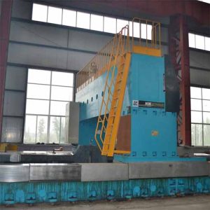
Machining services of gantry CNC milling and boring machine
Commonly used boring tools
Type of boring tool
According to the number of cutting edges, it can be divided into single-edged boring tools, double-edged boring tools and multi-edged boring tools; According to its machining surface, it can be divided into through hole boring tool, blind hole boring tool, stepped hole boring tool and end face boring tool; According to its structure, it can be divided into integral type, assembled type and adjustable type. படம் 1 shows the structure of a single-edge boring tool and a multi-edge boring tool.
Single edge boring tool
The structure of the single-edge boring tool head is similar to that of turning tools. The cutter head is installed in the tool holder, and the position of the cutter head is fixed with screws by manual manipulation according to the diameter of the hole being processed. The tool head is perpendicular to the axis of the boring bar to bore through holes, and the inclined installation can bore blind holes.
The single-edge boring tool has a simple structure, can correct the original hole axis deviation and small position deviation, and has a wide adaptability, which can be used for roughing, semi-finishing or finishing. எனினும், the size of the boring hole is guaranteed by manually adjusting the overhang length of the cutter head, which is troublesome. கூடுதலாக, only one main cutting edge participates in the work, so the production efficiency is low, and it is mostly used for single-piece small batch production.
Double edged boring tool
The double-edged boring tool has two symmetrical cutting edges, and the radial forces can cancel each other during cutting. The diameter and accuracy of the workpiece aperture are guaranteed by the radial dimension of the boring tool.
CNC boring
A boring tool has three basic elements: an indexable insert, a shank and a boring seat. The boring holder is used to hold the tool holder, and the holding length is usually about 4 times the diameter of the tool holder. The length that the insert-mounted shank extends from the boring seat is called the overhang (the unsupported part of the boring tool). The overhang determines the maximum depth of the boring hole and is the most important dimension of the boring tool. Excessive overhang can cause severe deflection of the shank, causing chattering, which damages the surface quality of the workpiece and may cause premature insert failure. These will reduce the processing efficiency.
For most machining applications, the user should choose a boring tool with the highest possible static and dynamic stiffness. The static stiffness reflects the ability of the boring tool to withstand the deflection caused by the cutting force, and the dynamic stiffness reflects the ability of the boring tool to suppress vibration.
The first part of this paper mainly analyzes the static stiffness of the boring tool. The information in this paper comes from the author’s research on the deflection of the boring tool. The deflection of the boring tool depends on the mechanical properties of the shank material, shank diameter and cutting conditions.
வெட்டு சக்தி
The cutting force acting on the boring tool can be measured with a rotating dynamometer. The measured forces include tangential force, feed force and radial force. Compared to the other two forces, the tangential force has the largest magnitude.
The tangential force acts perpendicular to the rake face of the insert and pushes the boring tool down. It is important to note that the tangential force acts near the tip of the insert and not on the center axis of the shank. The deviation of the tangential force from the centerline creates a moment arm (the distance from the centerline of the shank to the point of force), which creates a moment that causes the boring tool to twist relative to its centerline.
The feed force is the second largest force and acts parallel to the centerline of the shank, so it does not cause deflection of the boring tool. The radial force acts perpendicular to the centerline of the shank and pushes the boring tool away from the surface being machined.
எனவே, only tangential and radial forces will deflect the boring tool. An empirical algorithm that has been used for decades is: The feed force and radial force are about 25% மற்றும் 50% of the tangential force, respectively. Today, எனினும், this proportional relationship is not considered an “optimal algorithm” because the relationship between the individual cutting forces depends on the specific workpiece material and its hardness, cutting conditions, and nose radius.

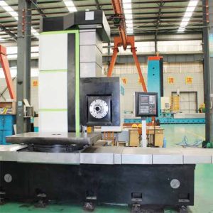
CNC machining service for planer type milling and boring machine
Boring tool deflection
The boring tool is similar to a cantilever beam with one end fixed (boring seat clamping part) and the other end unsupported (tool bar overhang), so the deflection of the boring tool can be calculated by the calculation formula of cantilever beam deflection:
y=(F×L3)/(3E×I)
In the formula: F is the resultant force; L is the overhang (unit: அங்குலங்கள்); E is the elastic modulus (அது, the Young’s modulus of the tool shank material) (unit: psi, pounds per square inch);
I is the moment of inertia of the section of the tool holder (unit: inch4).
The formula for calculating the moment of inertia of the section of the boring bar is:
I=(π×D4)/64
எங்கே: D is the outer diameter of the boring bar (unit: அங்குலங்கள்).
Example of deflection calculation of boring tool:
Processing conditions:
Workpiece material: AISI 1045 கார்பன் எஃகு, hardness HB250;
Depth of cut: 0.1″,
Feed: 0.008 inches/rev;
Shank diameter: 1″,
The elastic modulus of the blade: E=30×106psi,
The overhang of the shank: 4″.
(1) Calculation of tangential force
Ft=396000×depth of cut×feed rate×power constant=396000×0.1×0.008×0.99=313.6 lbs
(2) Calculation of radial force
Fr=0.308×Ft=0.308×313.6=96.6 lbs
(3) Calculation of resultant force
F=328.1 lbs
(4) Calculation of the moment of inertia of the section:
I=(π×D4)/64=0.0491 in.4
(5) Calculation of the deflection of the boring tool
y=(F×L3)/(3E×I)=0.0048″
The calculation formulas of the deflection of the boring tool and the moment of inertia of the section are analyzed. The following principles should be followed when boring:
(1) The overhang of the boring tool should be as small as possible. Because as the overhang increases, the deflection also increases. உதாரணத்திற்கு, when the overhang is increased by a factor of 1.25, the deflection will increase by a factor of nearly 2 while the shank OD and cutting parameters remain the same.
(2) The diameter of the boring bar should be as large as possible. Because when the diameter of the shank increases, the moment of inertia of its section will also increase, and the amount of deflection will decrease. உதாரணத்திற்கு, when the diameter of the shank is increased by a factor of 1.25, the deflection will decrease by a factor of nearly 2.5 with the same overhang and cutting parameters.
(3) When the overhang, the outer diameter of the tool bar and the cutting parameters remain unchanged, the use of a boring bar with a high elastic modulus material can reduce the deflection.
 English
 العربية
 中文(漢字)
 Čeština
 Dansk
Dansk Nederlands
 Suomi
Suomi Français
 Deutsch
 Italiano
 日本語
日本語 ಕನ್ನಡ
ಕನ್ನಡ 한국어
한국어 Português
 Русский
 Slovenčina
 Español
 Svenska
 Türkçe

