 English
 العربية
 中文(漢字)
 Čeština
 Dansk
Dansk Nederlands
 Suomi
Suomi Français
 Deutsch
 Italiano
 日本語
日本語 ಕನ್ನಡ
ಕನ್ನಡ 한국어
한국어 Português
 Русский
 Slovenčina
 Español
 Svenska
 Türkçe
5-axis machining of copper surface
5-சிக்கலான வளைந்த பகுதிகளின் அச்சு எந்திரம் (அலுமினிய கலவை, துருப்பிடிக்காத எஃகு, செம்பு, டைட்டானியம், வெளிமம், செம்பு)
Several elements of 5-axis machining of complex curved parts: curved surfaces and indexable milling inserts generated on CAD/CAM software
Almost all complex curved surfaces are processed by high-speed milling in production. The purpose is to improve production efficiency, reduce product cost, and at the same time improve the shape accuracy of the workpiece and reduce the surface roughness. In order to meet the needs of high-speed milling, the spindle of the machine tool almost without exception uses an electric spindle. The spindle speed is continuously variable according to the diameter of the tool used, and the speed range is from several thousand revolutions per minute to tens of thousands of revolutions per minute. The drive system of the sliding table is also different from conventional machining centers in high-speed milling. Commonly used systems include high-speed screw nut pair drive and linear motor drive, and the maximum feed speed can reach more than 100m/min.
5-தூண்டி வளைந்த மேற்பரப்பின் அச்சு எந்திரம்
When processing complex curved surfaces, இயந்திரக் கருவியின் CNC அமைப்பும் சில சிறப்புத் தேவைகளைப் பூர்த்தி செய்ய வேண்டும். உதாரணத்திற்கு, NC machining programs for complex curved surfaces are generally generated on CAD/CAM software. A curved surface program often requires several megabytes (பைட்) சேமிப்பு இடம், and it is no longer possible to transfer the NC program with a floppy disk. எனவே, the numerical control system must have the function of networking with other computer systems in order to directly receive numerical control programs from CAD/CAM. கூடுதலாக, எண் கட்டுப்பாட்டு அமைப்பு மேம்பட்ட கட்டுப்பாட்டு தொழில்நுட்பத்தையும் பின்பற்ற வேண்டும், முதலில், it requires the look-ahead (LookAhead) function. வேறு வார்த்தைகளில் கூறுவதானால், இயந்திர கருவி ஒரு குறிப்பிட்ட பாதையை செயலாக்கும் முன், தரவு அமைப்பு முன்கூட்டியே செயலாக்கப்பட வேண்டிய மேற்பரப்பை பகுப்பாய்வு செய்கிறது, according to the curvature of each point on the surface and the connection relationship between adjacent points. Properly adjust the feed speed of the machine tool to achieve the highest productivity while ensuring the accuracy of the workpiece. In order to reduce the dynamic error in the machining process, the new type of data system servo error correction no longer uses the previous series proportional differential integral (PID) regulator. Instead, it uses a state regulator that compensates for state parameters such as position and speed. The use of this regulator can completely eliminate the drive lag error, இடைவெளி அல்லது உராய்வு காரணமாக ஏற்படும் நேரியல் அல்லாத பிழையை ஈடுசெய்யவும், மற்றும் இயந்திர கருவியின் சில அதிர்வுகளை கூட ஈடுசெய்யும். பணிப்பொருளின் வடிவத் துல்லியத்தை மேம்படுத்துதல் மற்றும் மேற்பரப்பு கடினத்தன்மையைக் குறைத்தல் ஆகியவற்றின் தேவைகளைப் பூர்த்தி செய்ய.
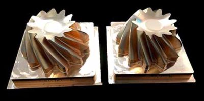
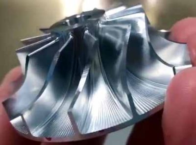
CNC milling cutter for machining curved surfaces
The tool system plays a decisive role in the production efficiency and processing quality when processing complex curved surfaces. வெட்டும் கருவி அமைப்பைத் தேர்ந்தெடுக்கும்போது, முதலில் செயலாக்கப்பட வேண்டிய பகுதிகளின் வடிவவியலில் இருந்து தொடங்க வேண்டும், மற்றும் நியாயமான முறையில் வெட்டும் கருவிகளின் வகைகளைப் பயன்படுத்தவும். As for the workpiece shown in Figure 1, the geometric variability of each part is very different. செயலாக்கத்திற்கு ஒரு பந்து முனை அரைக்கும் கட்டர் மட்டுமே பயன்படுத்தப்பட்டால், ஒரு சிறிய விட்டம் கொண்ட ஒரு பந்து முனை அரைக்கும் கட்டர் தேர்ந்தெடுக்கப்பட வேண்டும், இது செயலாக்க செயல்திறனை மேம்படுத்துவதை கடினமாக்குகிறது. கூடுதலாக, the arc radius of some parts is so small that it cannot be processed even with a small ball-end milling cutter. எனவே, உற்பத்தி திறன் மற்றும் பணிக்கருவி வடிவம் ஆகிய இரண்டின் தேவைகளையும் கணக்கில் எடுத்துக்கொள்வது, other types of milling cutters, இறுதி ஆலைகள் மற்றும் மூன்று முகம் அரைக்கும் வெட்டிகள் போன்றவை, must be equipped on the five-axis machining center for processing complex curved surfaces.
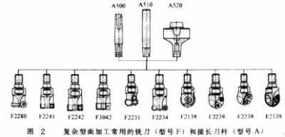
5-axis milling of different surfaces
படம் 2 shows some of the selected milling cutter types. அளவு அனுமதிக்கும் வரை, regardless of the shape of the milling tool, the cutting edge should be a machine-clamped indexable milling insert. Such knives can be combined with blades and bodies, and the blades and bodies can be produced by different companies. எனவே, a large-scale specialized production can be formed, which is not only conducive to improving the quality of the tool, but also conducive to reducing the production cost of the tool.
The tool life is closely related to the feed rate, cutting speed and milling depth. The optimal milling amount is often a small range, இது குறிப்பிட்ட கருவி மற்றும் பணிப்பொருளின் பொருளின் படி தீர்மானிக்கப்பட வேண்டும்.
கூடுதலாக, போன்ற வெட்டு உத்திகள்: Tool path planning, tool axis surface normal vector (the surface normal direction at this point) or along the surface tangent vector (surface tangent direction at this point) is also a key factor for processing complex surfaces. It not only affects the surface roughness of the processed workpiece, but also affects the shape and dimensional accuracy of the workpiece. படம் 3 shows the different cutting strategies used when machining a cylindrical curved surface. For milling in the circumferential direction, the tool path needs to be interpolated with two-axis linkage. When cutting along the generatrix direction, the tool only needs to perform single-axis interpolation. கூடுதலாக, different cutting methods have great differences in tool wear: The tool wear during down milling is significantly lower than that of up-down milling, மற்றும் ஒரே திசையில் அரைப்பதை விட, மறுபரிசீலனை அரைக்கும் போது ஏற்படும் தேய்மானம் மிக அதிகம்..
இயந்திர செயல்முறையின் நிலைத்தன்மையை மேம்படுத்துவதற்காக, the continuity of cutting must be ensured when optimizing the cutting strategy. அதே நேரத்தில், reduce the cutting motion and idle stroke as much as possible to shorten the milling time. When rough milling steel parts, it is necessary to ensure continuous down milling to minimize the peak value of the cutting edge during the cutting process.
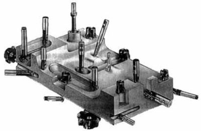
படத்தில் காட்டப்பட்டுள்ள பணிப்பகுதியை செயலாக்கும் போது 4, if the row cutting and milling track shown in Figure 5a is used for partition processing; கருவியின் இயக்கம் மிகவும் நியாயமற்றது, வெட்டு நிலைமைகள் மிகவும் திருப்தியற்றவை, the machining time is 33min, மற்றும் பணிப்பகுதியின் மேற்பரப்பு கடினத்தன்மை 6-9μm ஆகும். If the circle cutting track shown in Figure 5b is used instead for processing, செயலாக்க நேரம் சுமார் 27 நிமிடங்கள், and the roughness of the workpiece can also be reduced to 2 செய்ய 4 μm.