 English
 العربية
 中文(漢字)
 Čeština
 Dansk
Dansk Nederlands
 Suomi
Suomi Français
 Deutsch
 Italiano
 日本語
日本語 ಕನ್ನಡ
ಕನ್ನಡ 한국어
한국어 Português
 Русский
 Slovenčina
 Español
 Svenska
 Türkçe
Vid finbearbetning av tunna delar, skillnaden från grovbearbetning är att inverkan av spännkraft, skärverktyg och processparametrar på delens inre spänning måste beaktas fullt ut i efterbehandlingsprocessen. Samt påverkan av skärkraft och fräsvärme på detaljens struktur under fräsning, deformationen kontrolleras för att undvika deformationen som orsakas av effektivitetsförbättringen, vilket orsakar skada på detaljens noggrannhet och ytkvalitet.
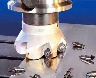
Urval av fräsar för fräsning av tunnväggiga aluminiumlegeringsdetaljer
Urval av skärverktyg för bearbetning av tunna delar
Att välja mer rimliga verktyg kan direkt förbättra produktionseffektiviteten. Fräsning av aluminiumlegeringsmaterial kräver inga höga verktygsmaterial. Allmänt, Det räcker med en hårdmetallfräs, och beläggningen kan vara obelagd eller diamantbelagd. Vid grovbearbetning, eftersom det inte är nödvändigt att överväga noggrannhet och kvalitetsfrågor, metallmaterialet kan avlägsnas så effektivt som möjligt, så ett verktyg med stor diameter kan väljas för att minska antalet passeringar och förkorta passtiden.
Dessutom, vid grovbearbetning, försök att välja tättande verktyg istället för glesa tandverktyg, vilket kan öka matningen per varv, och skärhastigheten kan ökas med samma hastighet. Vid finbearbetning, förutom att överväga problemet med högeffektivt materialavlägsnande, Problemet med kraft- och deformationskontroll av tunnväggiga komponenter under skärning bör också beaktas fullt ut.
Hårdmetallverktyg bör användas för bearbetning av tunnväggiga delar av höghållfast aluminiumlegering. Verktygets spånvinkel bör inte vara för liten, annars ökar skärdeformationen och friktionen, slitaget på rakan kommer att öka, och verktygets livslängd förkortas. Dessutom, valet av bågredien för verktygsspetsen bör vara lämpligt, och verktygets tänder bör inte vara för täta för att underlätta spånutsläpp. Det är fördelaktigt att ytterligare öka matningshastigheten, förhindra att det härdade lagret kallbearbetas, och förlänga verktygets livslängd.
Ställ in verktygsbanan för fräsning av tunna delar
Välj verktygsbana för fräsning av tunna detaljer
Ett mer effektivt sätt att öka hastigheten och effektiviteten är att optimera verktygsbanan, och säkerställ riktningen av verktygsbanan under höghastighetsskärning. Det är, verktygsbanan är så enkel som möjligt, med färre vändpunkter, och vägen så smidig som möjligt för att minska snabba riktningsändringar; Tomgångstiden bör minskas, och andelen skärtid i hela arbetsstycket bör ökas så mycket som möjligt;
Ska försöka använda slingfräsning, genom utan att avbryta skärprocessen och verktygsbanan. Minska in- och utskärningstiderna för verktyget, och få ett stall, effektiv bearbetningsprocess med hög precision.
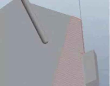
Verktygsbana för yta med liten krökningsradie
Verktygsbana för yta med liten krökningsradie
Vid höghastighetsbearbetning av stora och komplexa krökta ytor av integrerade konstruktionsdelar, när krökningen av den krökta ytan förändras kraftigt, riktningen för den maximala krökningsradien bör användas som optimal skärriktning; När krökningen av den krökta ytan ändras liten, krökningsradiens inverkan på skärriktningen försvagas. Det är bättre att välja skärriktningen med den längsta medellängden på en enda verktygsbana.
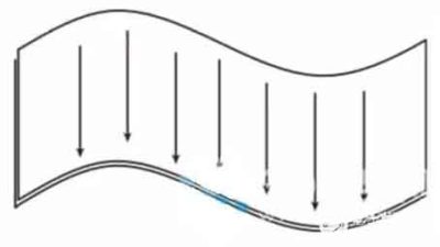
Horisontell verktygsbana för fräsning
Böjd verktygsbana med stor krökningsradie
Vid bearbetning av lutande plan, om horisontell skärning antas, skäravståndet för varje segment är mycket kort. Under fräsningsprocessen, spindeln behöver ändra riktning ofta, vilket resulterar i dålig skärstabilitet. Och för att fräsningen är lutande, horisontell matning kräver länkning av X- eller Y-axeln och Z-axeln, vilket inte bidrar till att öka skärhastigheten.

Välj parametrar för fräsning av tunna detaljer
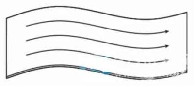
Horisontell horisontell verktygsbana för fräsning
Därför, för denna typ av fasbearbetning, verktygsbanan ska vara så parallell som möjligt med den längsta avfasningen. Inte bara verktygsbanan är längst, antalet reverseringstider är minst, men det enda verktyget skärs bara i X- och Y-planen. Rörelsen i Z-axelns riktning är anordnad utanför arbetsstyckets kontur, vilket kan minska verktygsskador även vid höghastighetsskärning.
Sned parallell verktygsbana för fräsning
Val av skärparametrar
Vid grovbearbetning, man kan i allmänhet välja en stor matningshastighet och ett lagom stort skärdjup, tillsammans med en medelhög skärhastighet “hög effekt” högeffektiv skärning, vilket kan uppnå en hög materialavlägsningshastighet, vilket i hög grad förbättrar produktionseffektiviteten. För efterbehandling, det är bara möjligt att öka hastigheten och öka antalet tänder. Att öka matningen per tand kan minska ytnoggrannheten, vilket resulterar i kvarvarande stress och deformation. Därför, “lätt skärning och snabb skärning” med hög skärhastighet och låg matning per tand används ofta för att säkerställa förbättringen av produktionseffektiviteten och noggrannheten och ytkvaliteten på produkterna.
Skärparametrar kan bestämmas genom skärning av finita elementanalys och skärtester. Ta ett portal CNC-bearbetningscenter med en maximal spindelhastighet på 24000r/min som ett exempel. Genom analys av Third Wave AdvantEdge programvara, i grovbearbetningsprocessen av tunnväggiga paneler, om du väljer φ25mm eller φ32mm indexerbara fräsar. För optimering av skärparametrar, spindelhastigheten bör ökas på lämpligt sätt, och urvalsintervallet är 12000~15000r/min; Matningen per tand och skärdjupet bör inte vara för stort, och de valbara områdena är 0,15 mm/z respektive 2–3 mm.
En del av simuleringsdata från frästest
Skärtestet kan utformas inom det valfria området för parametrarna som erhålls från finita elementanalysen, och skäreffektiviteten, ytsträvhet, och bearbetad yttopografi används som utvärderingskriterier, och de optimala skärparametrarna väljs slutligen.
Under den högeffektiva bearbetningsstrategin för tunnväggiga delar av aluminiumlegering, rätt val av ovan nämnda fräsverktyg, skärande verktyg, och fräsparametrar krävs också.