 English
 العربية
 中文(漢字)
 Čeština
 Dansk
Dansk Nederlands
 Suomi
Suomi Français
 Deutsch
 Italiano
 日本語
日本語 ಕನ್ನಡ
ಕನ್ನಡ 한국어
한국어 Português
 Русский
 Slovenčina
 Español
 Svenska
 Türkçe
Vad kan man göra med en 5-axlig fräsmaskin?
Det kan låta konstigt, men om renässanskonstnären hade bytt ut hammaren och mejseln mot en numerisk kontroll (CNC) och fräsmaskin, vi skulle ha tusentals statyer av David gjorda av alla typer av material idag.
Om du fortfarande tvivlar på att 5-axlig fräsning är en riktig konstform, klicka här eller här.
Oavsett om du skulpterar ett mästerverk av marmor eller fräser en blisk av titan – grundprincipen är densamma: Du börjar med ett block av materialet och tar bort de överflödiga bitarna tills bara målobjektet återstår. Självklart, detaljerna i denna process är mycket mer komplicerade, speciellt med 5-axlig fräsning.
Tillämpningar av 5-axlig CNC-fräsning
What is 5-axis CNC milling?
Put simply, with 5-axis milling, an object or the milling tool is moved simultaneously along five different axes by means of a CNC control. This enables very complex parts to be machined, which is why 5-axis technology has proven itself particularly in the aerospace industry.
dock, this is not the only reason that 5-axis technology has become widespread. Other factors are:
1 , A trend towards single-setup object processing (sometimes referred to as “done-in-one”) to reduce turnaround time and improve efficiency
2 , The possibility of preventing accidents at work by tilting the milling element or the milling table in a controlled manner, which also enables the process to be better coordinated with the geometry of the respective object
3 , The optimization of the tool life and the tool cycle as a side effect of the above-mentioned tilting function of the milling element or milling table by ensuring an optimal cutting position and a constant metal removal rate
Funktioner för 5-axlig CNC-fräsning
What about the axes in the 5-axis machining process?
We all know the story of Newton and the apple, but there is a story of the mathematician and philosopher René Descartes of similarly dubious origins.
Descartes was in bed (as mathematicians and philosophers do) when he noticed a fly buzzing through his room. He realized that he could describe the position of the fly in the three-dimensional space of the room with only three numbers, represented by the variables X, Y and Z.
This is the Cartesian coordinate system that is still in use today, more than three centuries after Descartes’ death. X, Y and Z therefore cover three of the five axes of the 5-axis machining process.
But what about the other two axes?
Imagine zooming in on Descartes ’fly in mid-flight. Instead of just describing their position as a point in three-dimensional space, we can also describe their orientation. When the fly changes direction, it does so in the same way as an airplane that tilts to maneuver. The fourth axis, A, describes its lateral rotation around its own axis as an axis of rotation around X (called “rolling” in technical terms).
Following on from the aircraft comparison, the vertical inclination of the fly upwards or downwards is described by the fifth axis, B, as the axis of rotation around Y (called “nodding” in technical terms).
The careful reader will no doubt infer the existence of a sixth axis, C, rotating around the Z axis. In our example this is the horizontal rotation of the fly to the left or right (called “yaw” in technical terms).
If you have difficulty visualizing the six axes described above, the diagram below should serve as a guide:
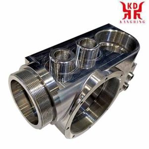
5-axis milling of machine housing
The axes A, B and C are arranged alphabetically to match the axes X, Y and Z accordingly. Although there are 6-axis CNC machines such as For example, the portal milling machine Zimmermann FZ 100, 5-axis configurations are more common, as the sixth axis usually offers hardly any additional use.
A final note on the conventions of axis designations: In a vertical machining center, the X and Y axes correspond to the horizontal plane, medan Z-axeln motsvarar det vertikala planet. I ett horisontellt bearbetningscenter, Z- och Y-axlarna byts om. Se diagrammet nedan:
5-axelkonfigurationer
Den specifika konfigurationen av en 5-axlig fräsmaskin avgör vilken av de tre rotationsaxlarna den använder.
Alltså z. B. en vridbordsmaskin med A-axeln (roterar runt X-axeln) och C-axeln (roterar runt Z-axeln), medan en vridhuvud maskin med en B-axel (roterar runt Y-axeln) och en C-axel (roterar runt Z-axeln) arbetar.
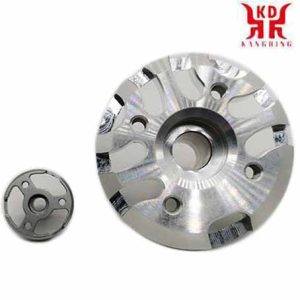
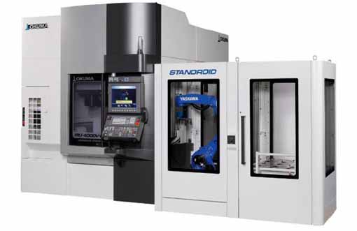
Inifrån av 5-axlarnas vridbord, vertikalt bearbetningscentrum för Okuma MU-4000V
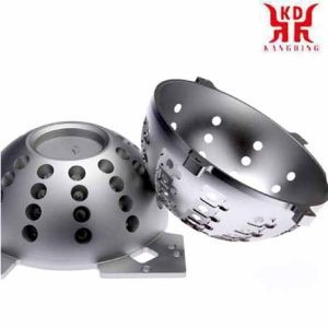
5-axelfräst lampskärm prototyp
Rotationsaxlarna i svängbordsmaskiner manövreras av bordets rörelse, medan maskiner med svänghuvud driver sina rotationsaxlar genom att rotera en spindel. Båda typerna har sina egna fördelar. Till exempel, swivel table machines offer larger processing chambers because the swivel spindle does not require significant space. Å andra sidan, swivel head machines can also process heavier parts because the table is always horizontal.
How many axes are required?
You may have heard of machining centers with seven, nine, or even eleven axes. Although so many additional axes seem hard to imagine, the explanation for such staggering numbers is actually quite simple.
“When you are dealing with machines that e.g. Till exempel, having more than one turning spindle increases the number of axes, ”explained Mike Finn, Senior Engineer Industrial Applications at Mazak America.
“For example, we have machines with an additional, second spindle and lower turrets. With these machines you have several axes: the upper turret has 4 yxor och det nedre tornet har 2 yxor, då har du två motsatta spindlar som också har 2 yxor. Sådana maskiner kan ha upp till 9 yxor, ”fortsatte Finn.
“Delarna du gör är fortfarande 5-axliga delar,” lade Wade Anderson till, produktspecialist och försäljningschef på Okuma America.
“En sådan komponent. B. en ventil för flygindustrin skulle lätt kunna tillverkas i vårt vertikala bearbetningscenter MU-5000, en 5-axlig maskin. Vi skulle också kunna bearbeta den här delen på en fleraxlig maskin med en B-rotationsaxel och två spindlar för två C-axlar vardera, plus standard X, Y- och Z-axlar. Det finns också det nedre tornet, som ger dig en andra X- och Z-axel. Så det finns fler bearbetningsaxlar tillgängliga, men själva delen kommer att ha samma geometri, sa Anderson.
Så hur många yxor behövs egentligen?
Som så ofta är fallet inom tillverkning, svaret på denna fråga beror på den specifika applikationen. Finn gav följande exempel:
"Ett turbinblad är en yta i fri form och kan vara mycket komplex. Den mest effektiva metoden för att bearbeta ett sådant objekt är 5-axlig bearbetning, där verktyget styrs i en spiral runt turbinbladets profil. 3-axelbearbetning är möjlig genom att fixera bladet i ett visst läge och sedan bearbeta ytan längs tre linjära axlar, men detta är vanligtvis inte den mest effektiva metoden. ”
Andersson höll med: “Det beror på geometrin hos respektive komponent om du behöver en 3, 4 eller 5-axlig konfiguration.”
dock, det är viktigt att notera att antalet axlar som krävs beror på aspekter som sträcker sig bortom objektet som ska bearbetas direkt. The target is the main factor, but it’s also about the long-term needs and goals of each customer, sa Anderson.
“A customer could show me a part, such as a titanium bracket for aerospace technology, and I could say, ‘This is a perfect part for a 5-axis machining center,’ but the customer may already be planning to make parts in the future that can be processed better with one of our MULTUS U machines. This multi-function machine may not be as optimally suited as a 5-axis machining center with regard to the current component, but it offers the customer the possibility of turning, shaft or chucker work that can also be applied to future components. ”
“Another aspect to consider is the dimensions of the processing chamber,” added Finn. “What are the maximum dimensions of an object that you can insert into the machine without affecting tool and position changes? It’s about understanding what is possible with the system and what is not. ”
5-axis machining vs. 3D utskrift
What are the advantages of 5-axis machining?
Choosing between 3-axis machining and 5-axis machining is a bit like deciding between a MacDonald’s quarter pounder and a T-bone steak; If cost is your only concern, then the first option is clearly a better option.
dock, if you compare 5-axis machining with 3 + 2-axelbearbetning, the decision is much more difficult.
5-axis vs 3 + 2-axel
In order to understand the subject, it is important to understand the difference between 5-axis machining and 3 + 2-axelbearbetning. The former – also called continuous or simultaneous 5-axis machining, åtföljs av kontinuerliga justeringar av skärverktygets inriktning längs alla fem axlarna för att hålla skärmunstycket optimalt vinkelrätt mot arbetsstycket.
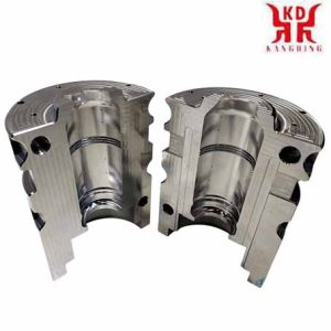
Demokomponent gjord av 6010 aluminium produceras på alla 5 axlar med en DMG MORI DMU50. Behandlingstid: 13 minuter.
Med den senare, å andra sidan – även kallad 5-sidig eller 3 + 2-axelbearbetning – ett 3-axligt program körs där fräsverktyget fixeras i en vinkel som bestäms av de två rotationsaxlarna. Om verktyget justeras om längs rotationsaxlarna mellan skärningarna, processen kallas “5-axel indexerad”; dock, det är fortfarande en av de 3 + 2-axelbearbetningsprocesser.
3 + 2-axeldemokomponent gjord av 6010 aluminium, tillverkad på en DMG MORI DMU50. Behandlingstid: 7 minuter.
Den största fördelen med 5-axlig kontinuerlig bearbetning jämfört med 5-axlig indexerad bearbetning är hastigheten, eftersom den senare måste stoppas varje gång verktyget justeras om, medan den förra inte gör det.
I princip, dock, det är möjligt att uppnå samma resultat med båda varianterna. (Läsare som inte håller med får gärna dela med sig av sina exempel på delar som endast kan bearbetas med kontinuerlig 5-axlig teknologi i kommentarsfältet under artikeln.)
Det bör också nämnas att hastighetsfördelen köps till priset av ökad verktygsaktivitet, vilket är förknippat med ökat slitage och ett ökat behov av krockdetektering. Detta är en av anledningarna till att kontinuerlig 5-axlig bearbetning är mer av en utmaning ur operativ synvinkel.
5-axis machining vs. 3D utskrift
3D tryckning eller additiv eller generativ tillverkning – är för närvarande ett hett ämne i produktionsvärlden, especially with regard to the comparison with subtractive manufacturing processes such as 5-axis machining.
Although it is sometimes suggested that these two methods are in competition with each other – especially by hardcore 3D fans who claim that the 3D – Technology will soon turn the entire manufacturing industry upside down -, From a more moderate point of view, additive and subtractive manufacturing processes appear rather than mutually complementary technologies.
“I don’t think additive manufacturing will completely take over the manufacturing landscape, but I think it offers opportunities to make parts that couldn’t have been made in the past,” said Finn. “There are still many parts that require subtractive machining. For example parts that have a very low roundness tolerance. ”
“It is possible to bring an element to a near net shape without any problems, but this element still has to be reworked in order to achieve sufficient tolerance,” added Finn.
Does that mean that the future of manufacturing lies in a hybrid production system consisting of 3D printing and 5-axis CNC – perhaps with a built-in coordinate measuring machine to check the dimensions?
Anderson was not sure: “The real application of 3D printing outside of a laboratory environment is not to have a combined system, but for example an LMD system (Laser Metal Deposition; German: laser metal deposition) and simultaneously a rotary or Milling machines that both do what they do best and combine both units with automation. ”
The point behind two separate systems is better powder and chip management.
“The amount of powder you need on an LMD facility to make a 30-pound part can be anywhere from 150-300 pounds of titanium,” said Anderson. “When that is put into a machine that combines all of the functions, it is next to impossible to recover and reuse the powder.”
Med andra ord: 3D printing and 5-axis machining are less in competition with one another than they are complementary to one another. “I think that additive manufacturing can immensely reduce the amount of roughing involved in manufacturing,” concludes Finn.
How to get the most out of 5-axis machining
It is not uncommon for the advantages of 5-axis technology to not be used to a sufficient extent.
Andersson höll med: “That breaks the heart of companies like ours: När vi ser ett företag som går all-in vid köp av sitt system och sedan bara använder en bråkdel av funktionerna vid driftsättningen av olika anledningar, t.ex. använder ett multifunktionellt system med fem eller fler axlar såsom ett 3-axligt system. Något sådant händer igen och igen. ”
"Ofta är detta fenomen relaterat till företagets HR-policy,” tillade Anderson. "Det handlar om att träna och förstå hur man använder ett system. Ibland är det svårt för de ansvariga att föreställa sig hur standardapplikationer kan varieras. T.ex. om inte respektive del också kunde bearbetas med en övre rotation, en lägre rotation, en huvudspindel och en motspindel samtidigt i en integrerad process. The possibilities may seem overwhelming to some and overwhelm them. ”
The importance of 5-axis control and software
Although having an industrial mechanic with the appropriate qualifications makes a significant contribution to utilizing the full potential of a 5-axis system, the system’s control system and software are just as important.
“With high-speed 5-axis machining, the servo drives on the system and the response time are very important in order to avoid erratic and inaccurate cuts during machining,” said Finn. “The system’s control system must be able to process the data quickly enough so that the tool can be guided over the object in a nice, smooth movement. You don’t want any jerky movements that can lead to deviations and irregularities. ”
”Mjukvaran som skapar de 5-axliga programmen måste också kunna generera snyggt, smidig kod så att systemet kan omvandla den till en smidig rörelse,säger Finn.
Att välja rätt CAD / CAM-paketet är därför avgörande för att få ut det mesta av din maskin.
“Till exempel, när du gör flygblisks, du måste arbeta med avancerade program,” said Anderson. “Om, å andra sidan, du tillverkar små aluminiumelement i en formgjuten form för ett bilföretag och behöver bara borra några hål i ett motorhus för att montera dem, det är såklart något helt annat.”
“Om du skär delar som ett CAM-system behöver skapa specifika skärprogram för, du bör investera i ett CAM-system som är skräddarsytt för din anläggnings kapacitet,” tillade Finn.
Avoidance of collisions in 5-axis systems
When creating 5-axis milling paths, there is usually a dilemma between higher cutting and feed speeds and minimizing the risk of accidents and falls. Fortunately, there are a number of software tools out there that can help neutralize these risks.
“With our collision avoidance software, you can upload a 3D model of the part and tools and the program will check for any risk of collision before the tool moves,” said Anderson. “If your device is modeled correctly, the collision will be prevented before the movement begins.”
“There is software on the market that can do machine simulations,” commented Finn. “This is extremely important, especially when it comes to more expensive parts. You don’t want collisions that would result in you having to scrap a part, injure someone or damage the machine. ”
“Vericut offers 3D virtual surveillance software that does the same thing but on an offline computer,” added Anderson. “So instead of running on the control system in real time, upload your part data to Vericut and it will examine all of your toolpaths and make sure the system will do exactly what you expect it to.”
Tool sensors in 5-axis systems
High productivity is an advantage of 5-axis machining. but it also increases the risk of errors, such as B. Using a damaged tool or the wrong tool. One way to minimize such errors is to use a tool sensor such as B. this BLUM laser on the DMG MORI DMU 50:
5-axis technology: everything in just one pass?
The term “Done in One” is a noble ideal in production: You load a block of material into a machine, run the program and receive a completely finished part. Like zero set-up time, Done-in-One is also a worthwhile goal, even if it ultimately cannot be achieved without compromising.
Regardless of this fact, 5-axis machining brings us much closer to the goal than any other process, because even 3D printed parts require post-processing. I detta sammanhang, the clamping technology represents a major limitation with regard to 5-axis machining.
“The clamping technology is immensely important in 5-axis machining,” says Anderson. “I can have the best system in the world, but if my clamping technology is lousy, I’ll never get the part out that I want at the end of the day.”
According to Finn, nyckeln till att övervinna detta hinder ligger i användningen av maskiner med mer än fem axlar:
“Vår INTEGREX-maskin z. B. kan utrustas med motspindlar och ett nedre fräsrevolver. Detta gör att delarna kan skäras på en spindel och sedan överföras till underspindeln för att bearbeta resten av delen. Detta gör att du i princip kan ladda ett block av råmaterial och lossa en färdig del i slutet. ”
Den verkliga konsten med 5-axlig fräsning
5-axelbearbetning erbjuder betydande fördelar såsom kortare genomloppstider, högre effektivitet och längre verktygslivslängd. dock, det är viktigt att förstå att dessa fördelar inte kan realiseras genom att bara köpa det senaste 5-axliga bearbetningscentret.
Att bemästra konsten med 5-axlig bearbetning kräver att man överväger en mängd olika faktorer. Om ämnet, Anderson sa följande:
”Om man ser till kundens problem, då är tekniska problem under bearbetningen ganska sällsynta. För det mesta, de problem de ställs inför kretsar kring saker som inte har med tillverkningstekniken att göra, utan snarare utbildningsfrågor och personalfrågor. översätt därför arbetsplanen till adekvata systemkontrollkommandon eller försäkra dig om att det finns tillräckligt med verktyg för att slutföra den del som har påbörjats innan bearbetning. De perifera delarna av processen utgör ofta en större utmaning än de tekniska frågorna i själva tillverkningen. ”