 English
 العربية
 中文(漢字)
 Čeština
 Dansk
Dansk Nederlands
 Suomi
Suomi Français
 Deutsch
 Italiano
 日本語
日本語 ಕನ್ನಡ
ಕನ್ನಡ 한국어
한국어 Português
 Русский
 Slovenčina
 Español
 Svenska
 Türkçe
Det ideala CNC-bearbetningsprogrammet ska inte bara säkerställa att kvalificerade arbetsstycken som överensstämmer med ritningarna bearbetas, men bör också göra det möjligt att använda CNC-maskinens funktioner på ett rimligt sätt och utnyttja dem fullt ut. CNC-maskinen är en mycket effektiv automationsutrustning. Dess effektivitet är 2 till 3 gånger högre än för vanliga verktygsmaskiner. Därför, för att ge full spel åt denna funktion hos CNC-verktygsmaskiner, man måste behärska dess prestanda, egenskaper, och driftmetoder. På samma gång, bearbetningsplanen måste fastställas korrekt före programmering.
Due to the difference in production scale, the processing plan for the same part is different. According to specific conditions, an economical and reasonable process plan should be selected.
(1) Division of processing procedures
Processing parts on CNC machine tools can be more concentrated in the process, and all processes should be completed as much as possible in one setup. Compared with ordinary machine tool processing, the division of processing procedures has its own characteristics, and there are two commonly used principles for division of procedures.
1. The principle of ensuring accuracy
Numerical control processing requires the process to be concentrated as much as possible, and often rough and fine processing are completed in one clamping. In order to reduce the influence of thermal deformation and cutting force deformation on the shape, position accuracy, dimensional accuracy and surface roughness of the workpiece, rough and finish machining should be carried out separately. For shaft or disc parts, rough machining will be performed first, leaving a small margin for finishing to ensure the surface quality requirements. På samma gång, for some box workpieces, in order to ensure the accuracy of hole machining, the surface should be processed first and then the hole should be processed.
2. Principles of improving production efficiency
Vid CNC-bearbetning, in order to reduce the number of tool changes and save tool change time, after all the parts that need to be processed with the same tool are completed, another tool should be used to process other parts. På samma gång, the idle stroke should be minimized. When processing multiple parts of the workpiece with the same tool, the shortest route should be used to reach each processing part.
In practice, the CNC machining process should be considered comprehensively according to the structural characteristics and technical requirements of specific parts.
(2) Determination of processing route
Machining route for turning cone parts
Vid CNC-bearbetning, the movement path and direction of the tool (strictly speaking, the tool position point) relative to the workpiece is called the machining route. Det är, the path that the tool travels from the tool setting point to the end of the machining program, including the path of cutting and the non-cutting idle strokes such as tool introduction and return. The determination of the processing route must first ensure the dimensional accuracy and surface quality of the processed parts, and secondly consider the simple numerical calculation, the shortest possible tool path, and the higher efficiency.
The following examples analyze the commonly used machining routes when machining parts with CNC machine tools.
1. Analysis of machining route for turning cone
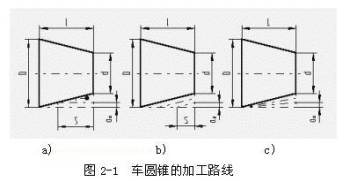
For turning the outer cone on the CNC lathe, assuming that the major diameter of the cone is D, the minor diameter is d, and the length of the cone is L, the machining route of the turning cone is shown in Figure 2-1.
According to the stepped cutting route in Figure 2-1a, two-cut rough turning, and the last one-cut fine turning; The final tool distance S of the two-cut rough turning must be accurately calculated, which can have similar triangles:
Design the cutting route of stepped parts
For this kind of processing route, the turning thickness is the same for rough turning, but the turning thickness is different for fine turning; På samma gång, the cutting path of the tool is the shortest.
According to the similar oblique cutting route in Figure 2-1b, it is also necessary to calculate the final tool distance S during rough turning, which can also be calculated from similar triangles:
The shortest path design of the tool cutting movement
According to this processing route, the cutting distance of the tool is relatively short.
According to the oblique line processing route in Figure 2-1c, only the amount of back tool ap is determined each time, instead of calculating the final tool distance, the programming is convenient. dock, the thickness of each cutting changes, and the cutting path of the tool is longer.
2. Analysis of machining route of turning arc
Use G02 (or G03) command to turn arc. If the arc is processed by turning once, the amount of knife is too large and it is easy to hit the knife. Därför, in the actual turning of arcs, multi-cutting is required, and a large amount of excess is removed first, and then the required arc is turned.
The following describes the common machining routes of turning arcs.
Turning arc for designing step cutting route
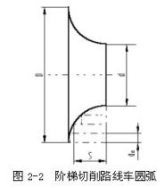
Figur 2-2 shows the step cutting route of turning arc. Det är, first rough turning is made into steps, and the arc is cut out with the final cut. In this method, after the turning thickness ap is determined, the final tool distance S of rough turning must be calculated accurately, det är, the intersection point of the arc and the straight line is calculated. In this method, the cutting movement distance of the tool is shorter, but the numerical calculation is more complicated.
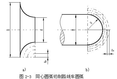
Figur 2-3 shows the concentric arc cutting route of turning arc. Det är, turning with different radius circles, and finally processing the required arc. This method is easier to determine the starting point and end point coordinates of the 90° arc after determining the amount ap of each tool. The numerical calculation is simple, and the programming is convenient, so it is often used. But when processing according to Figure 2-3b, the idle stroke time is longer.
Design a cutting path arc of concentric arcs
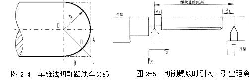
Figur 2-4 shows the cutting route of the turning cone method for turning arcs. Det är, first turning a cone, and then turning the arc. dock, it should be noted that if the starting point and end point of the cone are not determined well, the surface of the cone may be damaged, or the margin may be left too large. The determination method is shown in Figure 2-4. Connect OC to intersect the arc at D, and make the tangent AB of the arc through point D.
From the geometric relationship CD=OC-OD= -R=0.414R, this is the maximum cutting allowance when turning taper, det är, when turning taper, the processing route cannot exceed AB line. According to the relationship shown in the figure, AC=BC=0.586R can be obtained, so that the starting point and end point of the cone can be determined. When R is not too large, AC=BC=0.5R can be taken. The numerical calculation of this method is complicated, and the cutting path of the tool is short.
Turning the arc with the cutting path of the turning cone method
3. Analysis of Axial Feeding Distance When Turning Thread
When turning the thread, the feed of the tool along the thread direction should maintain a strict speed ratio relationship with the rotation of the workpiece spindle. Considering that the tool reaches the specified feed rate from the stopped state or drops from the specified feed rate to zero, the drive system must have a transition process. The length of the processing route along the axial feed, in addition to ensuring the thread length, should also increase the tool lead-in distance of δ1 (2~5mm) and the tool cutting distance of δ2 (1~2mm), som visas i figuren 2-5 . This is to ensure that when cutting threads, the tool will contact the workpiece after the speed increase is completed, and the tool will slow down after leaving the workpiece.
The machining route of the outer circle of the milled part
4. Analysis of Contour Milling Processing Route
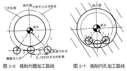
For continuous milling contours, especially when processing arcs, pay attention to the arrangement of cutting in and out of the tool, and try to avoid repeated processing at the junction, otherwise there will be obvious boundary milling marks. Som visas i figuren 2-6, when using circular interpolation to mill an outer circle, arrange the cutter to enter the circumferential milling process from the tangential direction. After the whole circle is processed, do not retract the tool directly at the tangent point, but let the tool move a certain distance. It is best to follow the tangential direction to avoid collision between the tool and the surface of the workpiece when the tool compensation is cancelled, causing the workpiece to be scrapped. When milling internal arcs, the principle of cutting in from the tangential direction should also be observed, and the transition arcs should be arranged to cut in and cut out, som visas i figuren 3-7. If the tool starts from the origin of the workpiece coordinate, its processing route is 1→2→3→4→5, so as to improve the machining accuracy and quality of the inner hole surface.
Design the route of machining part hole
5. Analysis of hole machining route with high position accuracy
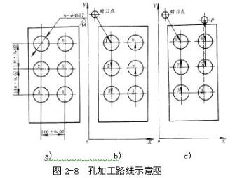
For hole machining that requires high precision in position accuracy, special attention should be paid to the arrangement of the hole processing sequence. Improper arrangement may bring in the backlash along the coordinate axis and directly affect the position accuracy. Som visas i figuren 2-8, Figure a is a part drawing. There are two processing routes for six holes of the same size processed on this part. When machining according to the route shown in figure b, the positioning direction of holes 5 och 6 is opposite to that of holes 1, 2, 3 och 4. The reverse clearance in the Y direction will increase the positioning error and affect the position accuracy of holes 5 och 6 and other holes. According to the route shown in Figure c, after processing 4 holes, move up a distance to point P, and then turn back to process 5 och 6 holes. På det här sättet, the direction is consistent, which can avoid the introduction of backlash and improve the position accuracy of holes 5 och 6 and other holes.
Design the processing route of the part surface
6. Analysis of the processing route of milling surface
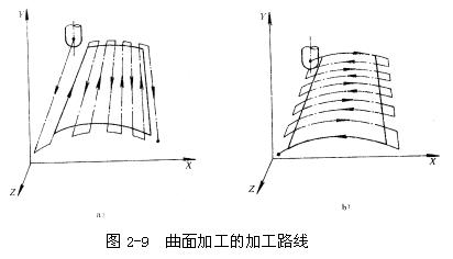
When milling a curved surface, a ball-end knife is commonly used for processing with the “wire cutting method”. The so-called wire cutting method means that the tangent track of the tool and the part contour is line by line, and the distance between the lines is determined according to the requirements of the machining accuracy of the part. For surface machining with open boundaries, two machining routes can be used. Som visas i figuren 2-9, for large engine blades, when the processing scheme of Figure 2-9a is used. Each time it is processed along a straight line, the calculation of the tool position point is simple, the program is few, the processing process conforms to the formation of the ruled surface, and the straightness of the bus can be accurately guaranteed. When the processing plan shown in Figure 2-9b is used, the data of this type of part is in accordance with the information given for easy inspection after processing. The accuracy of the impeller shape is high, but there are many procedures. Because the boundary of the surface part is open, there are no other surface restrictions, so the boundary of the surface can be extended, and the ball-end knife should start processing from outside the boundary.
The above has analyzed the commonly used processing routes in CNC machining through several examples. In actual production, the determination of the processing route should be based on the specific structural characteristics of the parts, comprehensive consideration and flexible use. The general principles for determining the processing route are: Under the condition of ensuring the machining accuracy and surface quality of the parts, shorten the machining route as much as possible to improve productivity.