 English
 العربية
 中文(漢字)
 Čeština
 Dansk
Dansk Nederlands
 Suomi
Suomi Français
 Deutsch
 Italiano
 日本語
日本語 ಕನ್ನಡ
ಕನ್ನಡ 한국어
한국어 Português
 Русский
 Slovenčina
 Español
 Svenska
 Türkçe
Komplexa konturer uppträder i verktygs- och formtillverkning, och är massproducerade produkter. Innan uppkomsten av CNC-verktygsmaskiner, smidesformar och formverktyg som används inom bilindustrin tillverkades huvudsakligen för hand. Efter 1970-talet, CNC-verktygsmaskiner har använts i stor utsträckning i verktygs- och formtillverkning. Grundkonturerna av komplexa profiler bearbetas vanligtvis genom fräsning, och de omgivande CNC-verktygsmaskinerna är initialt inställda på treaxlig länkage.
After entering the 1980s, five-axis milling machines have been widely used in complex surface processing. The contour of the workpiece after milling is very close to the final shape of the workpiece, but the last finishing process is still manual. In the late 1980s, high-speed cutting technology gradually developed and matured, and its application in industrial production has been continuously improved in terms of machine tools, cutting tools and other related technologies. Since high-speed cutting can double the feed speed, the feed pitch can be reduced without reducing production efficiency. This provides a prerequisite for improving the shape accuracy of the workpiece and reducing the surface roughness. För närvarande, most of the workpieces processed by high-speed milling no longer need the last manual processing procedure, but can be directly put into use.
5-axelbearbetning av komplexa profiler
New tool materials: such as alumina-based ceramics, silicon nitride-based ceramics, cermets, hårdmetall, especially the continuous development of superhard coatings, making hard face milling possible. The mold surface can be milled to shape after quenching, thereby avoiding deformation caused by quenching after milling. This not only simplifies the machining process, but also improves the accuracy of the workpiece.
Dessutom, with the application of precision forging in die manufacturing, the die blank after forging already has its designed basic shape, and the remaining machining allowance is insignificant compared with the milling of the entire blank. I detta fall, in addition to milling, it can also be processed by high-efficiency grinding. Compared with hard face milling, high-efficiency grinding can not only improve the shape accuracy of the workpiece, but also improve the surface roughness of the workpiece. There are many high-efficiency grinding methods, usually high-speed grinding with spherical grinding wheels and belt grinding with small-diameter belt wheels.
Type of milling cutter
Three-dimensional free-form surfaces in tools and molds are usually processed on a 5-axis machining center. Since the material of the workpiece is mostly alloy steel or tool steel, the structure of the machine tool and the numerical control system must consider the requirements of productivity and workpiece accuracy in the processing process, and make appropriate layout and optimization based on this. In order to ensure that the machine tool does not undergo too much deformation when cutting various mold materials, the machine tool stiffness should be the first priority when determining the machine layout. Larger axis machining center, most of a gantry structure, some small-sized five-axis machining center is also sometimes used high column structure.
Since the beginning of the 1990s, almost all complex shapes have been processed by high-speed cutting in production. Syftet är att förbättra produktionseffektiviteten, minska produktkostnaden, och samtidigt förbättra arbetsstyckets formnoggrannhet och minska ytjämnheten. In order to meet the needs of high-speed cutting, verktygsmaskinens spindel använder nästan utan undantag en elektrisk spindel. Spindelhastigheten är kontinuerligt variabel beroende på diametern på det använda verktyget, and the speed ranges from several thousand revolutions per minute to tens of thousands of revolutions per minute. The drive system of the sliding table is also different from conventional machining centers in high-speed cutting. Commonly used system with high-speed drive nut screw assembly and linear motor drive, a maximum feed speed can reach 100m / min or more.
The appearance drawing of CNC machining complex cavity surface
When processing complex surfaces, verktygsmaskinens CNC-system måste också uppfylla vissa speciella krav. Till exempel, CNC machining programs for complex surfaces are generally generated on CAD/CAM software. A profiled program often requires several megabytes (Byte) av lagringsutrymme, and it is no longer possible to transfer NC programs with a floppy disk. Därför, the CNC system must have the function of networking with other computer systems in order to receive the CNC program directly from the CAD/CAM. Dessutom, det numeriska styrsystemet måste också anta avancerad styrteknik, för det första, it requires the function of LookAhead. Med andra ord, innan verktygsmaskinen bearbetar ett visst spår, datasystemet analyserar ytan som ska bearbetas i förväg. According to the curvature of each point of the curved surface and the connection relationship of each adjacent point, the feed speed of the machine tool is appropriately adjusted to achieve the highest productivity under the premise of ensuring the accuracy of the workpiece. In order to reduce dynamic errors during processing, the new servo error correcting data using a conventional tandem system is no longer proportional integral derivative (PID) controller, instead of using the state regulator by compensating for the position and speed state parameters. Using this kind of regulator can completely eliminate the drive hysteresis error, kompensera för det olinjära felet som orsakas av gapet eller friktionen, och till och med kompensera vissa vibrationer i verktygsmaskinen. För att möta kraven på att förbättra arbetsstyckets formnoggrannhet och minska ytjämnheten.
Setting of the cutting path of the cavity surface
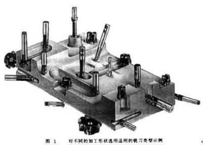
The tool system plays a decisive role in the production efficiency and processing quality when processing complex profiles. När du väljer ett skärverktygssystem, vi måste först utgå från geometrin hos de delar som ska bearbetas, och rimligtvis använda typerna av skärverktyg. Som visas i figuren 1, the geometry of each part is very different. Om endast en kuländfräs används för bearbetning, en kuländfräs med liten diameter måste väljas, vilket gör det svårt att förbättra bearbetningseffektiviteten. Dessutom, the arc radius of some parts is so small that it cannot be processed even with a small ball end mill. Därför, med hänsyn till kraven på både produktionseffektivitet och arbetsstyckets form, other types of milling cutters must be equipped on the five-axis machining center for processing complex profiles, såsom pinnfräsar och trefasfräsar.
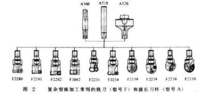
Figur 2 shows some types of milling cutters. Så länge storleken tillåter, regardless of the shape of the tool, the cutting edge should be a milling insert with a convertible clamp. Such knives can be combined in a variety of ways because of the blade and the body, and the blade and the body can be produced by different companies. Därför, large-scale specialized production can be formed, which not only helps to improve the quality of the tool, but also helps to reduce the production cost of the tool.
För närvarande, most of the indexable blades on the market use CVD coated carbide blades. In order to achieve higher pseudo-abrasion resistance, the indexable inserts are all multi-layered coatings. Bizhi Al2O3 can improve the chemical stability of the blade. TiN and TiCN can enhance the wear resistance of the blade. In order to enhance the sharpness of the blade, in addition to the low-temperature CVD method, the coating can also be produced by the PVD method. Some processing has very strict requirements on the blade. The blade must have a sharp cutting edge to reduce the roughness of the finished surface, but also have a high wear resistance to ensure the shape accuracy of the workpiece. I detta fall, a combination of multiple coatings must be used. In order to ensure that the use of some blades is foolproof, the number of coating layers can be as high as 100.
The life of the tool is closely related to the feed rate, cutting speed and depth of cut. The optimal cutting amount is often a small range, som bör bestämmas enligt det specifika verktyget och arbetsstyckets material.
Dessutom, skärstrategier som t.ex: The planning of the tool path, the normal vector of the tool axis surface (the normal direction of the surface at this point) or the different methods along the surface tangent vector (the tangent direction of the surface at this point), etc., are also a key factor for processing complex surfaces . Det påverkar inte bara ytråheten hos det bearbetade arbetsstycket, men påverkar också arbetsstyckets form och dimensionella noggrannhet. Figur 3 shows the different cutting strategies used when machining a cylindrical surface. For cutting in the circumferential direction, the tool path needs to be interpolated in two-axis linkage. Vid skärning längs generatrisriktningen, verktyget behöver bara utföra enaxelinterpolation. Dessutom, olika skärmetoder har stora skillnader i verktygsslitage. The tool wear during down milling is significantly lower than that of up milling, och slitaget under fram- och återgående fräsning är mycket större än vid enkelriktad fräsning.
För att förbättra stabiliteten i bearbetningsprocessen, when optimizing the cutting strategy, the continuity of the cutting must be ensured, and the cutting motion and idle stroke must be reduced as much as possible in order to shorten the cutting time. When the rough milling of steel, must ensure continuous climb milling, to minimize the peak of the cutting blade during cutting of the amount of fluctuation.
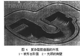
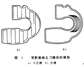
Vid bearbetning av arbetsstycket som visas i figur 4, if the row cut trajectory section processing shown in Figure 5a is used; Rörelsen av verktyget är mycket orimlig, skärförhållandena är mycket otillfredsställande, the processing time is 33min, och arbetsstyckets ytråhet är 6-9μm. If you switch to the circle-cutting path shown in Figure 5b for processing, handläggningstiden är ca 27 minuter. På samma gång, the roughness of the workpiece can also be reduced to 2 ~ 4μm.