Prečo je sústruženie závitov také náročné?
Požiadavky na sústruženie závitov sú vyššie ako bežné sústružnícke operácie. Rezná sila je spravidla vyššia, a polomer rezného konca závitovej vložky je menší a slabší.
Pri spracovaní vlákien, rýchlosť posuvu musí presne zodpovedať stúpaniu závitu. Za smolu 8 závity/palec (tpi), nástroj sa musí posúvať rýchlosťou posuvu 8 otáčky/palec resp 0.125 palce/revolúcia. V porovnaní s bežnými sústružníckymi aplikáciami (kde typická rýchlosť posuvu je približne 0,012ipr), rýchlosť posuvu sústruženia závitu je 10 krát vyššia. Sila na špičke závitovej spracovacej vložky môže byť 100 do 1,000 krát vyššia.

Sústruženie závitov s viaczubovou závitovou vložkou
obrázok 2: Viaczubové vložky, s viacerými zubami závitu v sérii, účinnosť spracovania závitov sa môže zlepšiť, ale rezná sila je vyššia.
Koncový polomer, ktorý nesie túto silu, je všeobecne 0.015 palce, kým polomer konvenčnej sústružníckej doštičky je 0.032 palce. Pre závitové nástroje, polomer je prísne obmedzený koreňovým polomerom povoleného tvaru závitu (jeho veľkosť určuje príslušná závitová norma). Je tiež obmedzený požadovaným rezným úkonom, pretože materiál neznesie proces rezania pri bežnom sústružení, inak dôjde k deformácii závitu.
Výsledkom je vyššia rezná sila a užší rozsah koncentrácie sily: Vložky na obrábanie závitov znášajú oveľa väčšie namáhanie ako bežné sústružnícke nástroje.

Sústruženie závitu s priečnym podávaním
Porovnanie nožov čiastočného a plného profilu
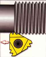
Čiastočné profilové vložky, niekedy označovaný ako “bez vrchnej časti” vložky, rezať drážky závitu bez prepichovania alebo prepichovania závitu. (Pozri obrázok 1) Nástroj môže vytvárať sériu závitov, až po najhrubšiu smolu-tj, najmenší počet závitov na palec, ktorý je povolený silou polomeru konca čepele.
Koncový polomer je navrhnutý tak, aby bol dostatočne malý, aby čepeľ mohla spracovať rôzne stúpania. Pre závity s malým stúpaním, Koncový polomer sa javí ako príliš malý. To znamená, že čepeľ musí pri obrábaní preniknúť hlbšie. Napríklad, obrábanie 8 Vlákno TPI s vložkou čiastočného profilu vyžaduje hĺbku vlákna 0.108 palce. Rovnaké vlákno vyrobené s úplným čepeľou vyžaduje iba zadanú hĺbku 0.81 palce. Preto, Celý profil vložky môže vytvoriť silnejšie vlákno. Navyše, Prevádzka obrábajúcich vlákien s úplným profilom vložky je možné vykonať v 4 menej krokov.

Rezanie vlákna metódou priečneho rezania bokom
Čepeľ
Čepeľ s viacerými zubami má nepretržite sériu zubov, a hĺbka rezania akéhokoľvek zuba v závite je hlbšia ako predchádzajúci zub. (Pozri obrázok 2) S týmito vložkami, Počet operácií potrebných na strojové vlákno sa dá znížiť o 80%. Životnosť nástroja je oveľa dlhšia ako vložky s jedným centrom, Pretože konečný zub spracováva iba polovicu alebo jednu tretinu kovu daného vlákna.
Avšak, Kvôli ich vysokej reznej sile, Odporúča sa používať tieto vložky na spracovanie tenkostenných častí, pretože sa môže vyskytnúť chatovanie. Navyše, Štruktúra pre obrábanie obrobkov s týmito vložkami musí mať dostatočný výbavu závitu, aby všetky zuby mohli opustiť rezanie.

Otáčanie závitu nastavením uhol špirály čepele
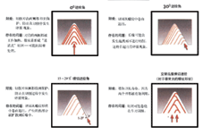
Obrázok 3: Výber metódy prierezového krmiva má veľký vplyv na účinnosť spracovania vlákna

Vlastný nástroj na rezanie vlákna pre frézovacie vlákna
Obrázok 4: Bokové priečne rezanie neprodukuje čipy v tvare V, ale vyrába čipy podobné čipom pri bežnom obrate.
Napájať
Hĺbka rezania každého priechodu, Alebo podávate každé vlákno, je veľmi kritický pri spracovaní vlákien. Každý pripojený prevádzkový kanál musí zapojiť väčšú časť reznej hrany čepele. Ak je krmivo na priechod konštantný (Táto metóda sa neodporúča), Rezacia sila a rýchlosť odstraňovania kovov sa drasticky zvýši z predchádzajúceho prechodu na ďalší.
Napríklad, Pri používaní konštantného prívodu .010 palce / Rýchlosť spracovania kanála 60 ℃ Tvar závitu, Druhý materiál stopy je odstránený 3 krát prvú skladbu. Rovnako ako pri každej nasledujúcej operácii, Množstvo odstráneného kovu naďalej exponenciálne rastie.
Aby sa zabránilo tomuto zvýšeniu množstva odstraňovania a udržali realistickejšiu reznú silu, Pri každej operácii by sa mala znížiť hĺbka vlákna.
Metóda podvádzania vlákna
Existujú najmenej štyri metódy kŕmenia vlákna. (Pozri obrázok 3) Len málo ľudí zistilo, aký veľký vplyv má jedna z týchto metód na efektivitu závitových operácií.
• Radiálny závit priečneho posuvu
•Aj keď to môže byť najbežnejšie používaná metóda na spracovanie závitov, je to skutočne najmenej odporúčaná metóda. Keďže nástroj je podávaný radiálne (kolmo na stredovú čiaru obrobku), kov sa odstráni z oboch strán boku závitu, výsledkom sú triesky v tvare V. Takéto triesky sa ťažko lámu, takže tok triesok je problém. Navyše, v dôsledku vyššieho tepla a tlaku na oboch stranách konca čepele, životnosť nástroja je zvyčajne kratšia ako pri iných metódach priečneho posuvu.
• krížový posuv boku závitu
Pri tejto metóde, priečny smer je rovnobežný s jedným z bokov závitu, čo vo všeobecnosti znamená, že nástroj sa pri 30 °C posúva v priamom smere. Štiepky sú podobné tým, ktoré sa vyrábajú pri bežnom sústružení. (Pozri obrázok 4.) V porovnaní s radiálnym priečnym rezom, triesky vyrobené týmto spôsobom sa ľahšie tvarujú a ľahko sa odvádzajú z reznej hrany, s lepšou tepelnou difúziou. Avšak, pri tejto metóde priečneho podávania, zadná hrana čepele sa trie o bok zuba a nereže. Tým sa spália vlákna, čo má za následok slabú drsnosť povrchu a dokonca chvenie.
• Upravený priečny rezný posuv bokov zubov závitu (odporúčané)
Táto metóda je podobná metóde podávania priečneho rezu bokov závitu, až na to, že priečny uhol rezu je menší ako uhol závitu - tzn, menej ako 30 ℃. Táto metóda si zachováva výhody metódy priečneho rezatia vlákna, a zároveň sa vyhnúť problémom spôsobeným koncovým okrajom čepele. Prierezový uhol 291/2 ℃ všeobecne prináša najlepšie výsledky, Ale v skutočnej prevádzke, Priekopnícky uhol v rozsahu 25 ~ 291/2 ℃ je prijateľný.
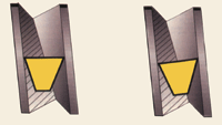
Obrázok 5: Nastavením uhla špirály čepele, ako “sklonený” čepeľ vpravo, Uhol vôle pod prednými a zadnými okrajmi čepele môže byť vyvážený, ktoré môžu produkovať rovnomernejšie opotrebenie.
• Alternatívne bok boku závitu priečny rezací prívod
Táto metóda sa striedavo podáva pozdĺž dvoch boku vlákna, takže na vytvorenie vlákna používa dva boky čepele. Táto metóda môže zaručiť dlhšiu životnosť nástroja, Pretože sa používajú obe strany konca čepele. Ale môže tiež spôsobiť problémy s tokom čipov -
Tento problém môže ovplyvniť drsnosť povrchu a životnosť nástroja. Táto metóda sa zvyčajne používa iba pre veľké ihrisko a (cisársky) lichobežné a šikmé štvorstranné vlákna.
Kompenzácia uhlia zlína
Niektoré vložky na obrábanie nití a systémy držiaka nástrojov majú schopnosť presne nakloniť vložku v smere rezania zmenou uhol špirály. Táto funkcia môže produkovať nekvalitné vlákna, pretože zabraňuje treniu čepele o bok vlákna. Môže tiež poskytnúť dlhšiu životnosť nástroja, pretože rezná sila je rovnomerne rozložená po celej dĺžke reznej hrany.
Neexistuje žiadna rezacia vložka, ktorá je takto naklonená- Spôsob, ako urobiť špičkovú hranu rovnobežnú s strednou čiarom obrobku- Pod hlavou a koncový okraj čepele sa vytvorí nerovnaký uhol výšky. (Pozri obrázok 5) Najmä pre hrubšie ihrisko, Táto nerovnosť môže spôsobiť trenie v boku zubov.
Nastaviteľný systém umožňuje, aby sa uhol čepele naklonil cez polohu náradia (Zvyčajne so spieľami). Presné nastavenie dosiahne podobné uhly vedúceho a koncového okraja, Zabezpečenie rovnomerného rozvoja opotrebenia čepele.
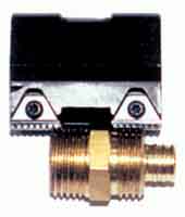
Obrázok 6: Tento vlastný nástroj na rezanie vlákna sa používa na stroj dve nezávislé vlákna na sústruhu so šiestimi otočenými. V minulosti, vlákna boli spracované po jednom. Tu použitá vložka bola v skutočnosti pôvodne určená pre nožnice na mletie nití, ale používa sa tu ako otáčanie vložky
Miniaturizácia a špecializácia vložiek na rezanie nití
Nástroje s vymeniteľnými doštičkami na sústruženie vnútorných závitov na otvoroch s priemerom približne 0.3 palce sú teraz dostupné na trhu.
Obrábanie takýchto malých otvorov do závitov sústružením má mnoho výhod. Kvalita závitu, ktorý sa má obrábať, je zvyčajne relatívne vysoká, štruktúra čepele umožňuje vytekanie triesok z otvoru a zriedkavo poškodzuje závit, a čepeľ je možné indexovať, takže cena nástroja je nízka.
Typy slinutého karbidu používané v týchto aplikáciách sú vo všeobecnosti také, ktoré umožňujú spracovanie pri nižších povrchových rýchlostiach. Na obrábanie vnútorných závitov v malých otvoroch, Obmedzenia obrábacích strojov sú vo všeobecnosti iné problémy ako nízke povrchové rýchlosti.
Technologický pokrok, ktorý ľudia dosiahli, rozšíril rozsah použitia nástrojov na sústruženie závitov, a otáčanie vnútorných nití na malé otvory je jedným z príkladov. Avšak, Napriek rozšíreniu rozsahu aplikácie štandardných nástrojov, Výrobcovia sa stále musia stretnúť s konkrétnymi problémami, čo vytvára priestor pre existenciu prispôsobených nástrojov. (Pozri obrázok 6) Špeciálny nástroj vyvinutý v spolupráci s dodávateľom nástroja je voľba, ktorú nemožno ignorovať pri hľadaní správneho nástroja na závity pre konkrétnu úlohu.
 English
 العربية
 中文(漢字)
 Čeština
 Dansk
Dansk Nederlands
 Suomi
Suomi Français
 Deutsch
 Italiano
 日本語
日本語 ಕನ್ನಡ
ಕನ್ನಡ 한국어
한국어 Português
 Русский
 Slovenčina
 Español
 Svenska
 Türkçe

