 English
 العربية
 中文(漢字)
 Čeština
 Dansk
Dansk Nederlands
 Suomi
Suomi Français
 Deutsch
 Italiano
 日本語
日本語 ಕನ್ನಡ
ಕನ್ನಡ 한국어
한국어 Português
 Русский
 Slovenčina
 Español
 Svenska
 Türkçe
Dimensions of machined parts drawings: standard tolerances and basic deviations, surface roughness, accuracy, плоскостность, position, параллелизм, coaxiality, и т. д..
| Shape and position tolerance | Position degree | Parallelism | Concentricity | Verticality | Full jump accuracy | Symmetry | Flatness | Cylindricity | Roundness | Roughness |
| symbol | ||||||||||
| measurement accuracy | 0.001 | 0.001 | 0.001 | 0.001 | 0.001 | 0.001 | 0.001 | 0.001 | 0.001 | Ra0.01 |
| Точность обработки | 0.03 | 0.005 | 0.005 | 0.01 | 0.01 | 0.01 | 0.002 | 0.01 | 0.005 | Ra0.04 |
Symbol of surface roughness of parts
The concept of part surface roughness
На поверхности детали имеются выступы и впадины с небольшим расстоянием между ними., а микрогеометрические характеристики, образуемые ею, называются шероховатостью поверхности.. При обработке деталей на станке с ЧПУ, образуется за счет следов инструмента, оставляемых им на поверхности детали, и пластической деформации поверхностного металла при резке и распиловке на станках с ЧПУ..
Шероховатость поверхности деталей также является техническим показателем оценки качества поверхности деталей.. Это влияет на соответствующие свойства., точность работы, износостойкость, устойчивость к коррозии, уплотнение, появление, и т. д.. частей.
Код, символ и знак шероховатости поверхности
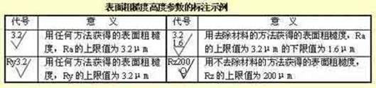
ГБ/Т 131-1993 указывает код шероховатости поверхности и его обозначение. Обозначения на чертеже, обозначающие шероховатость поверхности деталей, приведены в таблице ниже..
Параметры оценки шероховатости поверхности деталей::
1) Среднее арифметическое отклонение контура (Ра)
В пределах длины выборки, среднее арифметическое абсолютного значения смещения контура. The value of Ra and the sampling length l. See table.
2) Maximum profile height (Rz)
The distance between the top line of the contour peak and the bottom line of the contour peak within the sampling length.
Примечания: The Ra parameter is preferred when using it.
Marking requirements for surface roughness
1) Example of code labeling of surface roughness
When the surface roughness height parameters Ra, Rz, Ry are marked with numerical values in the code, except that the parameter code Ra can be omitted. The other parameters need to be marked with the corresponding parameter code Rz or Ry before the parameter value. See the table for labeling examples.
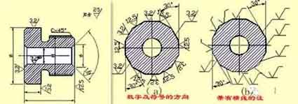
2) The method of marking the numbers and symbols in the surface roughness of the surface roughness
Marking method of surface roughness symbols on drawings
1) Код шероховатости поверхности (symbol) обычно следует отмечать на видимой контурной линии, граница размеров или их выносная линия, а кончик символа должен указывать на поверхность снаружи материала.
2) Направление цифр и символов в коде шероховатости поверхности должно быть отмечено соответствующим образом..
2) Maximum profile height (Rz)
The distance between the top line of the contour peak and the bottom line of the contour peak within the sampling length.
Примечания: The Ra parameter is preferred when using it.
Marking requirements for surface roughness
1) Example of code labeling of surface roughness
When the surface roughness height parameters Ra, Rz, Ry are marked with numerical values in the code, except that the parameter code Ra can be omitted. The other parameters need to be marked with the corresponding parameter code Rz or Ry before the parameter value. See the table for labeling examples.
2) The method of marking the numbers and symbols in the surface roughness of the surface roughness
Marking method of surface roughness symbols on drawings
1) Код шероховатости поверхности (symbol) обычно следует отмечать на видимой контурной линии, граница размеров или их выносная линия, а кончик символа должен указывать на поверхность снаружи материала.
2) Направление цифр и символов в коде шероховатости поверхности должно быть отмечено соответствующим образом..
Пример маркировки шероховатости поверхности
На этом же рисунке, каждая поверхность обычно маркируется кодом (symbol) только один раз, и как можно ближе к соответствующей размерной линии. Когда пространство узкое или неудобно маркировать, это может привести к ярлыку. Когда все поверхности деталей имеют одинаковые требования к шероховатости поверхности., их можно равномерно обозначить в правом верхнем углу чертежа. When most of the surfaces of the parts have the same surface roughness requirements, the most used code (symbol) can be marked on the upper right corner of the drawing at the same time, and the word “the rest” shall be added. The height of the uniformly marked surface roughness code (symbol) and explanatory text should be 1.4 times that of the drawing mark.
Continuous surfaces on parts, surfaces of repeated elements (such as holes, зубы, канавки, и т. д.), and the same surface that is not continuous with thin solid lines. Код шероховатости поверхности (symbol) number is only noted once.
When there are different surface roughness requirements on the same surface, thin solid lines should be used to draw the dividing line, and the corresponding surface roughness code and size should be noted.
When the tooth (tooth) shape is not drawn on the working surface of gears, threads, и т. д., the surface roughness code (symbol) notation method.
The working surface of the center hole, the working surface of the keyway, the surface roughness code of the chamfer, and the rounded corner can be simplified and marked.
When the parts need to be partially heat-treated or partially plated (coated), thick dotted lines should be used to draw the range and mark the corresponding dimensions. It can also be written on the horizontal line of the long side of the surface roughness symbol.
Numbers and symbols in surface roughness
Standard tolerance and basic deviation
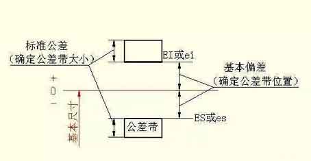
5. Standard tolerance and basic deviation
In order to facilitate production, realize the interchangeability of parts and meet different usage requirements, the national standard “Limits and Fits” stipulates that the tolerance zone is composed of two elements: standard tolerance and basic deviation. The standard tolerance determines the size of the tolerance zone, and the basic deviation determines the location of the tolerance zone.
1) Standard tolerance (IT)
El valor de la tolerancia estándar está determinado por el tamaño básico y la clase de tolerancia. El nivel de tolerancia es una marca para determinar la precisión del tamaño. La tolerancia estándar se divide en 20 niveles, a saber, IT01, IT0, IT1, …, IT18. La precisión de su tamaño disminuye de IT01 a IT18. Los valores específicos de las tolerancias estándar se pueden encontrar en las normas correspondientes.
Basic deviation of CNC machining
2) Desviación básica
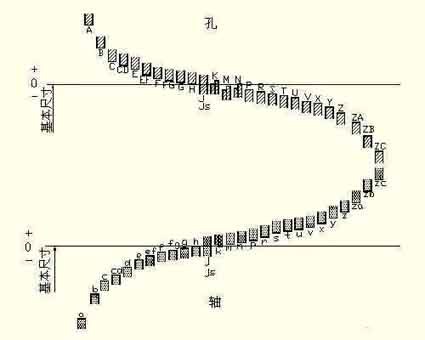
Базовое отклонение относится к верхнему или нижнему отклонению зоны допуска относительно положения нулевой линии в стандартном пределе и регулировке., и обычно относится к отклонению вблизи нулевой линии. Когда зона допуска находится выше нулевой линии, базовое отклонение – это наименьшее отклонение; Напротив, это верхнее отклонение. Хэй 28 основные отклонения в сумме, а кодовые названия выражаются латинскими буквами, с прописными буквами в качестве отверстия и строчными буквами в качестве оси.
Это видно из диаграммы ряда основных отклонений.:
Основное отклонение A~H отверстия и основное отклонение k~zc вала являются нижним отклонением.; The basic deviation K~ZC of the hole and the basic deviation a~h of the shaft are the upper deviation; The tolerance zones of JS and js are symmetrically distributed on both sides of the zero line, and the upper and lower deviations of the hole and shaft are +IT/2 and -IT/2 respectively. The basic deviation series diagram only shows the position of the tolerance zone, not the size of the tolerance. Поэтому, one end of the tolerance zone is an opening, and the other end of the opening is defined by a standard tolerance.
The basic deviation and standard tolerance, according to the definition of dimensional tolerance, have the following calculation formulas:
ES=EI+IT or EI=ES-IT
ei=es-IT or es=ei+IT
Код зоны допуска отверстия и вала состоит из кода основного отклонения и кода класса зоны допуска..