Протяжка алюминиевого сплава, нержавеющая сталь, детали из медных и титановых сплавов:
Протяжка – высокоэффективный метод отделки.. Помимо протяжки круглых отверстий, он также может прошивать сквозные отверстия и внутренние шпоночные пазы различной формы поперечного сечения., как показано на рисунке 7-19. Достижимый класс допуска для протяжки круглых отверстий — IT9~IT7., и значение шероховатости поверхности составляет Ra1,6 ~ 0,4 мкм..
1. Broaching can be regarded as planing with multiple planers arranged in order of high and low, как показано на рисунке 7-20. The structure of the round hole broach is shown in Figure 7-21, and the functions of each part are as follows:

Several different broaching hole shapes
The shank of the broach: It is the part where the broach is clamped by the knife clamp of the broach.
The neck diameter of the broach is the smallest: when the broaching force is too large, it generally breaks here, which is convenient for welding repair.
The transition cone of the broach: guide the broach into the hole being machined.
The leading part of the broach: to ensure a smooth transition of the workpiece to the cutting part, и в то же время, check whether the aperture before pulling is too small to prevent the first tooth from being damaged due to excessive load.
The cutting part of the broach: including rough cutting and fine cutting, it undertakes the main cutting work.
The leading part of the broaching knife. When the broaching cutter teeth cut away from the workpiece, it prevents the workpiece from sagging, scratching the machined surface and damaging the cutter teeth.

Способ протяжки круглых отверстий
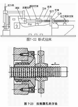
The horizontal broaching machine is shown in Figure 7-22. The machine body is equipped with a hydraulic drive cylinder, and the right end of the piston rod is equipped with a follower bracket and a knife holder to support and clamp the broaching knife. Before work, the broaching knife is supported on the roller and the tail bracket of the broach, and the workpiece is penetrated by the left end of the broach. When the tool holder clamps the broaching knife to move linearly to the left, the workpiece rests on the “support”, and the broaching knife can complete the cutting process. The linear movement of the broaching knife is the main movement, and the feed movement is completed by the lifting of each tooth of the broaching knife.

Method of broaching internal groove
(1) Broaching round holes is shown in Figure 7-23. The broaching hole diameter is generally 8~125mm, and the length to diameter ratio of the hole is generally not more than 5. В целом, precise pre-processing is not required before broaching, and broaching can be done after drilling or rough boring. If the end face of the workpiece is not perpendicular to the hole axis, the end face is pressed against the spherical washer of the broaching machine. Under the action of the broaching force, the workpiece and the spherical washer are slightly rotated, so that the axis of the hole is automatically adjusted to the same direction as the axis of the broach, which can prevent the broach from breaking.
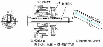
(2) Broaching the inner keyway as shown in Figure 7-24a. The keyway broach is flat, with teeth on the upper part. The correct position of the workpiece and the broaching knife is ensured by the guiding element. The cylinder 1 of the broaching knife guide element (Figure 7-24b) is inserted into the end hole of the broaching machine, the cylinder 2 is used to hold the workpiece, and the slot 3 is for the broaching knife.
 English
 العربية
 中文(漢字)
 Čeština
 Dansk
Dansk Nederlands
 Suomi
Suomi Français
 Deutsch
 Italiano
 日本語
日本語 ಕನ್ನಡ
ಕನ್ನಡ 한국어
한국어 Português
 Русский
 Slovenčina
 Español
 Svenska
 Türkçe

