 English
 العربية
 中文(漢字)
 Čeština
 Dansk
Dansk Nederlands
 Suomi
Suomi Français
 Deutsch
 Italiano
 日本語
日本語 ಕನ್ನಡ
ಕನ್ನಡ 한국어
한국어 Português
 Русский
 Slovenčina
 Español
 Svenska
 Türkçe
Com o aumento no design de peças curvas complexas e multifacetadas, 5-a usinagem de eixos será responsável por uma proporção crescente da usinagem CNC. Porque a usinagem CNC de 5 eixos adiciona dois graus de liberdade de rotação, aumenta a dificuldade de cálculo de simulação de movimento de usinagem CNC e verificação de interferência de ferramenta, especialmente ao usinar peças com formas extremamente complexas. Portanto, in order to ensure that 5-axis CNC machine tools perform high-efficiency and high-quality milling processing, the design of 5-axis machining tool path generation and interference checking software will become a major issue.
The feature projection method is suitable for 5-axis CNC machining tool interference processing, aquilo é, the machining surface is discretized into a series of surface feature points. Se a interferência da ferramenta ocorre pode ser julgada pelo fato de o ponto de característica entrar no interior da superfície da ferramenta. Ao mesmo tempo, the machining surface and the tool surface are projected onto a specific plane, and only the feature detection points in the curved surface area of the enveloping tool projection graph are checked for interference, o que melhora a eficiência da detecção de interferência.
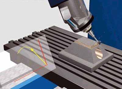
Evite a interferência da ferramenta no fresamento de 5 eixos
1. Inspection method for tool interference
Coordenar o sistema e coordenar a transformação
Como mostrado na figura 1, the local coordinate system L of 5-axis circular cutter milling is represented as XL axis, Eixo yl e eixo zl. O eixo YL sempre aponta para a direção de corte f do contato da ferramenta (referred to as CC point) Ol. The ZL axis points to the normal direction n of the surface, and the XL axis is determined by the right-hand rule of the YL axis and the ZL axis. A ferramenta geralmente gira em torno do eixo XL do eixo ZL para o eixo YL por um ângulo de chumbo (ângulo do calcanhar) um, and rotates around the ZL axis one by one side slip angle b. Além disso, o sistema de coordenadas da ferramenta t (XT, Yt, Zt) também pode ser definido no ponto de localização da ferramenta (CL Point para curta) Ot. The YT axis points to the direction of the line connecting the CL point and the CC point. The ZT axis is the tool axis vector direction, and the XT axis is the direction determined by the right-hand rule of the YT axis and the ZT axis. The coordinate origin is located at the tool center point (ou seja, CL Point) Ot. Para simplificar a verificação de interferência, A superfície da ferramenta com uma forma relativamente regular é usada como referência para verificação de interferência. The machined surface is discretized to express the shape of the surface in the form of a set of characteristic points. Os dados originais desses pontos de características são expressos no sistema de coordenadas mundiais w, Portanto, os dados do ponto de característica devem primeiro ser transformados do sistema de coordenadas mundiais w (OW-XW, É, Zw) para o sistema de coordenadas local l (Ol-xl, Yl, Zl) ). Em seguida, é transformado do sistema de coordenadas local l para o sistema de coordenadas da ferramenta t (OT-XT, Yt, Zt).
Método de verificação de interferência
Se a ferramenta e a cabeça de energia foram selecionadas, O tamanho do sistema de ferramentas (ferramenta e cabeça de energia) é conhecido. Whether the tool system interferes with the machined surface can be determined by judging whether the characteristic point P enters the inside of the tool surface. Como mostrado na figura 2, É a relação posicional entre o sistema de ferramentas e a superfície usinada quando a faca de anel é processada. No sistema de coordenadas da ferramenta, Deixe a coordenada do ponto característico P ser pi (Xpt, Ypt, Zpt). De acordo com as diferentes partes combinadas do sistema de ferramentas, O valor da coordenada Zpt do ponto característico P é dividido em 4 seções para julgamento. Os detalhes são os seguintes:
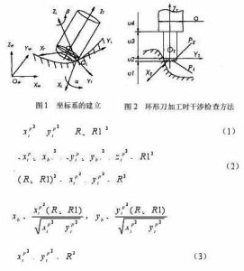
5-axis milling stroke setting formula
Quando o ponto de característica P está dentro do intervalo de U1, Nenhuma interferência ocorrerá.
Quando o ponto característico P está no intervalo de U2, Existem duas situações, and the torus is divided into two parts:
The small cylindrical part P1 and the circular ring part P2. Quando o ponto de característica está envolvido na parte cilíndrica P1, A interferência da ferramenta ocorre, aquilo é, it is satisfied
onde r representa o raio da ferramenta, e R1 representa o raio do anel da ferramenta circular.
Quando o ponto de característica está envolvido no anel da parte P2, A interferência da ferramenta também ocorre, aquilo é, it is satisfied
no estilo
If the feature point P does not enter the parts P1 and P2, Nenhuma interferência de ferramenta ocorrerá.
Quando o ponto característico P está dentro do alcance de U3, Quando a distância entre o ponto característico P e o eixo ZT é menor que o raio da ferramenta, A interferência da ferramenta ocorre, o que está satisfeito
De outra forma, Nenhuma interferência de ferramenta ocorrerá.
When the characteristic point P is in the range of u4, A situação é a mesma que a de 3, as long as the tool radius R in the formula (3) is replaced with the power head radius d/2 for judgment.