Palavras-chave: Usinagem CNC de núcleos de molde, Usinagem CNC
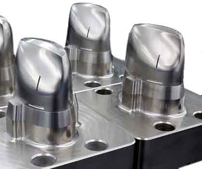
O núcleo e a cavidade do molde geralmente possuem várias superfícies de forma livre, que são muito adequados para processamento em máquinas-ferramentas CNC. O processo de usinagem CNC é bastante diferente do processo comum. Este artigo combina o projeto do processo de usinagem NC do núcleo do molde de decorações de produtos infantis, analisa e resume as características do processo de usinagem NC do molde, e fornece uma referência para o projeto do processo NC do molde.
The CNC machining process refers to the sum of various methods and technical means used when machining parts with CNC machine tools, which is applied to the entire CNC machining process. Because CNC machining has the characteristics of high processing efficiency, stable quality, relatively low technical requirements for workers, and one-time clamping can complete the processing of complex curved surfaces. Portanto, the application of CNC machining in the mold manufacturing industry is more and more widespread, and its status is becoming more and more important. The quality of CNC process design will directly affect the dimensional accuracy and surface quality of CNC machining dimensions, the length of machining time, the consumption of materials and labor, and even directly affect the safety of machining. The following example analyzes the CNC machining process of typical mold forming parts.
1. Product analysis
The product exemplified in this article is a decoration for children’s products, and the material is ABS. It can be seen from the product picture (Figura 1) that the product has a relatively simple structure, with a flat surface, semi-circular holes on the side and multiple round holes on the top. Since the product is an ornament and is not a precise structural part, the appearance quality of the product is higher, and the dimensional tolerance is not strict.

Usinagem CNC de núcleos de molde
2. Structure and analysis of molded parts
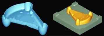
After obtaining the solid modeling or engineering drawing of the product, the mold can be designed using the CAD function in Pro/ENGINEER, NX or MasterCAM. The designed mold core is shown in Figure 2.
The mold core has the following characteristics:
(1) The size of the core blank is 200×170×65mm, the size after processing is 160.8×126.6×35.8mm, and the material is S136 steel.
(2) The height of the core glue position of the mold is 35.8mm, and the rounded corners at the intersection of the elliptical surface and the triangular surface are small, only R1mm. It is more difficult to directly process these positions with a milling cutter, and electrical discharge machining can be used to meet the requirements.
Because the dimensional tolerance of the product is not high, the core can be directly processed by CNC machine tools.
3. Process analysis
There is a certain difference between CNC machining technology and traditional machining technology. Since most CNC machine tools do not have the processing capability, every detail of the machining process must be determined in advance, and the machining is automatically completed according to the programmed program. Portanto, the processing technology must be analyzed in detail before programming, and the corresponding processing procedures must be designed.

Children’s ABS decoration products
(1). Process benchmark selection
CNC machining mostly adopts the principle of process concentration. Portanto, when selecting process benchmarks, appropriate benchmark elements should be selected as much as possible to reduce the number of clamping and improve processing efficiency and processing accuracy;
Ao mesmo tempo, when selecting the positioning datum, it is necessary to refer to the requirements of the drawing to make the process datum coincide with the design datum and reduce the error caused by the datum not overlapping.
In this example, the workpiece blank is a rectangular parallelepiped blank after grinding. Parallelism, perpendicularity and dimensional accuracy have been guaranteed. Portanto, the opposite sides of the length and width can be selected as the reference in the horizontal direction (XY direction); the bottom surface can be selected as the reference in the height direction (Z direction). Ao mesmo tempo, find a pair of tool datums on the machine tool to ensure that the programmed height datum, which is the Z0 point of the workpiece coordinate system, can still be accurately found after the tool is changed. These datum planes are no longer processed in the CNC machining process, as the machining datum can ensure the accuracy and uniformity of the datum.
(2). Choice of clamping method
During milling, the clamping methods of the workpiece generally include clamping by pressing plates and bolts, clamping by machine flat-nose pliers, and clamping by special fixtures. The mold core is a one-piece production order, and special fixtures are generally not used; The size of the mold core is 200×170×65mm, which is a small workpiece. Portanto, machine flat-nose pliers are selected for clamping. When using machine flat-nose pliers, the height of the core is 35.8mm. Portanto, the height of the top surface of the blank from the jaws of the flat-nose pliers after clamping should be greater than 35.8mm, and the bottom surface can be cushioned with a contour pad.

Milling processing sequence
(3). Processing sequence arrangement
Parts processed on CNC machine tools are generally divided into processes according to the principle of process concentration, aquilo é, each process should include as much processing content as possible. The process division methods are divided according to the used tools, divided according to the number of installations, divided according to rough and fine machining or divided according to the processing position. This example is a mold core, which belongs to single-piece production. Portanto, process concentration is the principle when arranging the processing sequence to reduce the number of tool changes and improve processing efficiency.
Whether the processing sequence is arranged reasonably, directly affects the processing quality, processing efficiency and processing cost. When selecting the processing sequence, it is necessary to combine the positioning reference and clamping method of the part according to the rough condition and the part structure. The key points need to be considered to ensure that the rigidity of the workpiece is not damaged during processing, reduce deformation, and ensure processing quality.
The blank material of the mold core is a rectangular parallelepiped, and the parting surface of the product has a large cutting amount. Rough machining must be carried out first, and then semi-finishing and finishing are completed. After the parting surface is processed, the top surface, the contact surface and the glue position are finished in order.
(4). Tool selection
The choice of cutting tools is one of the important contents in the CNC machining process. The machining tool not only affects the machining efficiency of the machine tool, but also directly affects the machining quality of the parts. Because the spindle speed and range of CNC machine tools are much higher than ordinary machine tools, and the output power of the spindle is relatively large. Portanto, compared with traditional machining methods, higher requirements are placed on CNC machining tools, which require high precision, força elevada, good rigidity and high durability, and require stable dimensions and easy installation and adjustment. CNC tools are one of the prerequisites for improving processing efficiency. Its selection depends on the geometry of the processed parts, material conditions, fixtures and the rigidity of the selected tools of the machine tool.
The material of the mold core is S136 steel, and the hardness is about 220HB;
Flat-nose pliers are used for blank clamping, which provides sufficient rigidity. Portanto, cemented carbide milling cutters are used for the processing of this core. The tool parameters are as follows:
(1) Round cutter with a diameter of 30mm and a radius of 5mm;
(2) Round-end knife with a diameter of 16mm and a radius of 0.5mm;
(3) Ball-end knife with a radius of 5mm;
(4) Flat-bottomed end mill with a diameter of 8mm.
4. Numerical control machining process based on MaterCAM
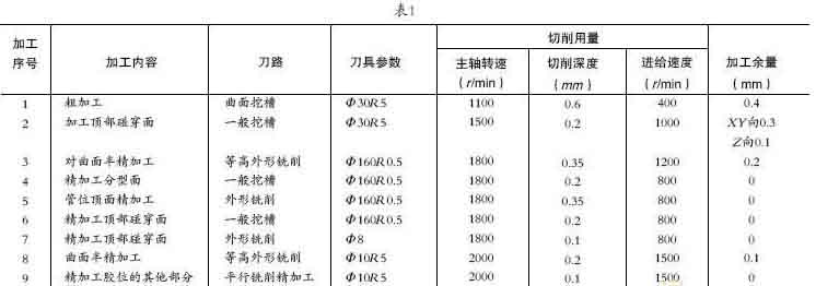
MaterCAM software is a CAD/CAM system based on the PC platform. Because it has low hardware requirements, flexible operation, easy to learn and easy to use, it is widely used in mechanical processing, mold manufacturing, automobile industry and aerospace industry. It has the functions of two-dimensional geometric design, three-dimensional surface design, tool path simulation and processing entity simulation. This example uses MasterCAM 9.1 for tool path programming. The processing sequence is shown in Table 1.
The above processing steps have been verified by actual processing, which proves that the processing effect is good, and the dimensional accuracy and surface processing quality meet the requirements of the drawings.
5. Analysis and summary
(1) CNC machine tools have obvious advantages in processing mold forming parts with complex curved surfaces. As long as the process design is reasonable, more than 80% of the processing volume can be completed.
(2) CNC machining of molds is generally rapid prototype small batch production. Portanto, general-purpose fixtures are usually used for clamping, and multiple processes are completed in one clamping. Portanto, in process design, the principle of process concentration should be adopted to make the process as concentrated as possible. Ao mesmo tempo, minimize the number of tool changes to reduce standby time and improve machine tool utilization.
(3) Mold forming parts can generally be completed through three processes: rough machining → semi-finishing → finishing. In process design, attention must be paid to the selection of positioning datum, try to ensure the coincidence of positioning datum and design datum, and reduce errors caused by inconsistent datums. Ao mesmo tempo, the choice of positioning reference should make the setting of the workpiece coordinate system simple.
(4) When selecting a tool, comprehensive consideration should be given to many factors such as the machine tool, workpiece material and design requirements. The setting of tool parameters should be based on the parameters improved by the tool manufacturer, and corresponding modifications should be made according to the processing conditions to maximize the potential of the tool. On the premise of ensuring that the tool does not interfere with the workpiece, try to shorten the length of the tool to reduce tool vibration, extend tool life, and improve machining accuracy.
 English
 العربية
 中文(漢字)
 Čeština
 Dansk
Dansk Nederlands
 Suomi
Suomi Français
 Deutsch
 Italiano
 日本語
日本語 ಕನ್ನಡ
ಕನ್ನಡ 한국어
한국어 Português
 Русский
 Slovenčina
 Español
 Svenska
 Türkçe

