O que pode ser feito com uma fresadora de 5 eixos?
Pode parecer estranho, mas se o artista renascentista tivesse trocado o martelo e o cinzel por um controle numérico (CNC) e fresadora, teríamos hoje milhares de estátuas de David feitas de todos os tipos de materiais.
Se você ainda tem dúvidas de que a fresagem de 5 eixos é uma verdadeira forma de arte, por favor clique aqui ou aqui.
Esteja você esculpindo uma obra-prima em mármore ou fresando um pedaço de titânio – o princípio básico é o mesmo: Você começa com um bloco do material e remove as peças em excesso até que reste apenas o objeto alvo. Claro, os detalhes deste processo são muito mais complicados, especialmente com fresamento de 5 eixos.
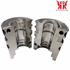
Applications of 5-axis CNC Milling
What is 5-axis CNC milling?
Put simply, with 5-axis milling, an object or the milling tool is moved simultaneously along five different axes by means of a CNC control. This enables very complex parts to be machined, which is why 5-axis technology has proven itself particularly in the aerospace industry.
No entanto, this is not the only reason that 5-axis technology has become widespread. Other factors are:
1 , A trend towards single-setup object processing (sometimes referred to as “done-in-one”) to reduce turnaround time and improve efficiency
2 , The possibility of preventing accidents at work by tilting the milling element or the milling table in a controlled manner, which also enables the process to be better coordinated with the geometry of the respective object
3 , A otimização da vida útil da ferramenta e do ciclo da ferramenta como efeito colateral da função de inclinação do elemento de fresagem ou mesa de fresagem acima mencionada, garantindo uma posição de corte ideal e uma taxa de remoção de metal constante
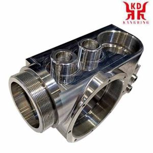
Funções de fresagem CNC de 5 eixos
E quanto aos eixos no processo de usinagem de 5 eixos?
Todos nós conhecemos a história de Newton e a maçã, mas há uma história do matemático e filósofo René Descartes de origens igualmente duvidosas.
Descartes estava na cama (como fazem os matemáticos e os filósofos) quando ele notou uma mosca zumbindo em seu quarto. Ele percebeu que poderia descrever a posição da mosca no espaço tridimensional da sala com apenas três números., representado pelas variáveis X, S e Z.
Este é o sistema de coordenadas cartesianas que ainda está em uso hoje, mais de três séculos depois de Descartes’ morte. X, Y e Z cobrem, portanto, três dos cinco eixos do processo de usinagem de 5 eixos.
Mas e os outros dois eixos?
Imagine dar um zoom na mosca de Descartes em pleno vôo. Em vez de apenas descrever a sua posição como um ponto no espaço tridimensional, também podemos descrever sua orientação. Quando a mosca muda de direção, faz isso da mesma forma que um avião que se inclina para manobrar. O quarto eixo, A, descreve sua rotação lateral em torno de seu próprio eixo como um eixo de rotação em torno de X (chamado de “rolamento” em termos técnicos).
Na sequência da comparação de aeronaves, a inclinação vertical da mosca para cima ou para baixo é descrita pelo quinto eixo, B, como o eixo de rotação em torno de Y (chamado de “acenar com a cabeça” em termos técnicos).
The careful reader will no doubt infer the existence of a sixth axis, C, rotating around the Z axis. In our example this is the horizontal rotation of the fly to the left or right (called “yaw” in technical terms).
If you have difficulty visualizing the six axes described above, the diagram below should serve as a guide:
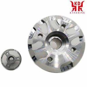
5-fresamento de eixo da carcaça da máquina
The axes A, B and C are arranged alphabetically to match the axes X, Y and Z accordingly. Although there are 6-axis CNC machines such as For example, the portal milling machine Zimmermann FZ 100, 5-axis configurations are more common, as the sixth axis usually offers hardly any additional use.
A final note on the conventions of axis designations: In a vertical machining center, the X and Y axes correspond to the horizontal plane, while the Z axis corresponds to the vertical plane. In a horizontal machining center, the Z and Y axes are swapped. See the diagram below:
5-axis configurations
The specific configuration of a 5-axis milling machine determines which of the three axes of rotation it uses.
So z. B. a swivel table machine with the A-axis (rotating around the X-axis) and the C-axis (rotating around the Z-axis), while a swivel head machine with a B-axis (rotating around the Y-axis) and a C -Axis (rotating around the Z-axis) is working.
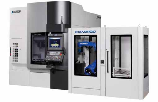
Inside view of the swivel table of the 5-axis, vertical machining center of the Okuma MU-4000V
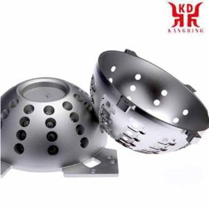
5-protótipo de abajur fresado com eixo
The axes of rotation in swivel table machines are operated by the movement of the table, while swivel head machines operate their axes of rotation by rotating a spindle. Both types have their own advantages. Por exemplo, swivel table machines offer larger processing chambers because the swivel spindle does not require significant space. Por outro lado, swivel head machines can also process heavier parts because the table is always horizontal.
How many axes are required?
You may have heard of machining centers with seven, nine, or even eleven axes. Although so many additional axes seem hard to imagine, the explanation for such staggering numbers is actually quite simple.
“When you are dealing with machines that e.g. Por exemplo, having more than one turning spindle increases the number of axes, ”explained Mike Finn, Senior Engineer Industrial Applications at Mazak America.
“For example, we have machines with an additional, second spindle and lower turrets. With these machines you have several axes: the upper turret has 4 eixos e a torre inferior tem 2 eixos, então você tem dois fusos opostos que também têm 2 eixos. Essas máquinas podem ter até 9 eixos, ”continuou Finn.
“As peças que você faz ainda são peças de 5 eixos,” acrescentou Wade Anderson, especialista de produto e gerente de vendas na Okuma America.
“Um componente como. B. uma válvula para a indústria aeroespacial poderia ser facilmente fabricada em nosso centro de usinagem vertical MU-5000, uma máquina de 5 eixos. Também poderíamos usinar esta peça em uma máquina multieixos com um eixo de rotação B e dois fusos para dois eixos C cada, mais o padrão X, Eixos Y e Z. Há também a torre inferior, que fornece um segundo eixo X e Z. Portanto, há mais eixos de usinagem disponíveis, mas a peça em si terá a mesma geometria, ”disse Anderson.
Então, quantos eixos são realmente necessários?
As is so often the case in manufacturing, the answer to this question depends on the particular application. Finn gave the following example:
“A turbine blade is a free-form surface and can be very complex. The most efficient method of machining such an object is 5-axis machining, in which the tool is guided in a spiral around the profile of the turbine blade. 3-axis machining is possible by fixing the blade in a certain position and then machining the surface along three linear axes, but this is usually not the most efficient method. ”
Anderson agreed: “It depends on the geometry of the respective component whether you need a 3, 4 or 5-axis configuration.”
No entanto, it is important to note that the number of axes required depends on aspects that extend beyond the object to be processed directly. The target is the main factor, but it’s also about the long-term needs and goals of each customer, ”disse Anderson.
“A customer could show me a part, such as a titanium bracket for aerospace technology, and I could say, ‘This is a perfect part for a 5-axis machining center,’ but the customer may already be planning to make parts in the future that can be processed better with one of our MULTUS U machines. This multi-function machine may not be as optimally suited as a 5-axis machining center with regard to the current component, but it offers the customer the possibility of turning, shaft or chucker work that can also be applied to future components. ”
“Another aspect to consider is the dimensions of the processing chamber,” added Finn. “What are the maximum dimensions of an object that you can insert into the machine without affecting tool and position changes? It’s about understanding what is possible with the system and what is not. ”
5-axis machining vs. 3Impressão D
What are the advantages of 5-axis machining?
Choosing between 3-axis machining and 5-axis machining is a bit like deciding between a MacDonald’s quarter pounder and a T-bone steak; If cost is your only concern, then the first option is clearly a better option.
No entanto, if you compare 5-axis machining with 3 + 2-usinagem de eixo, the decision is much more difficult.
5-axis vs 3 + 2-eixo
In order to understand the subject, it is important to understand the difference between 5-axis machining and 3 + 2-usinagem de eixo. The former – also called continuous or simultaneous 5-axis machining, is accompanied by continuous adjustments to the alignment of the cutting tool along all five axes in order to keep the cutting nozzle optimally perpendicular to the workpiece.
Demo component made of 6010 aluminum produced on all 5 axes using a DMG MORI DMU50. Processing time: 13 minutos.
With the latter, on the other hand – also called 5-sided or 3 + 2-usinagem de eixo – a 3-axis program is executed in which the milling tool is fixed at an angle determined by the two axes of rotation. If the tool is realigned along the rotational axes between cuts, the process is called “5-axis indexed”; no entanto, it is still one of the 3 + 2-axis machining processes.
3 + 2-axis demo component made of 6010 alumínio, produced on a DMG MORI DMU50. Processing time: 7 minutos.
The main advantage of 5-axis continuous machining over 5-axis indexed machining is speed, pois este último deve ser parado toda vez que a ferramenta é realinhada, enquanto o primeiro não.
Em princípio, no entanto, é possível obter os mesmos resultados com ambas as variantes. (Os leitores que discordam podem compartilhar seus exemplos de peças que só podem ser usinadas com tecnologia contínua de 5 eixos na seção de comentários abaixo do artigo.)
Também deve ser mencionado que a vantagem da velocidade é adquirida ao preço do aumento da atividade da ferramenta, que está associado ao aumento do desgaste e ao aumento da necessidade de detecção de acidentes. Esta é uma das razões pelas quais a usinagem contínua de 5 eixos é um desafio maior do ponto de vista operacional.
5-axis machining vs. 3Impressão D
3Impressão D ou fabricação aditiva ou generativa – é atualmente um tema quente no mundo da produção, especially with regard to the comparison with subtractive manufacturing processes such as 5-axis machining.
Although it is sometimes suggested that these two methods are in competition with each other – especially by hardcore 3D fans who claim that the 3D – Technology will soon turn the entire manufacturing industry upside down -, From a more moderate point of view, additive and subtractive manufacturing processes appear rather than mutually complementary technologies.
“I don’t think additive manufacturing will completely take over the manufacturing landscape, but I think it offers opportunities to make parts that couldn’t have been made in the past,” said Finn. “There are still many parts that require subtractive machining. For example parts that have a very low roundness tolerance. ”
“It is possible to bring an element to a near net shape without any problems, but this element still has to be reworked in order to achieve sufficient tolerance,” added Finn.
Does that mean that the future of manufacturing lies in a hybrid production system consisting of 3D printing and 5-axis CNC – perhaps with a built-in coordinate measuring machine to check the dimensions?
Anderson was not sure: “The real application of 3D printing outside of a laboratory environment is not to have a combined system, but for example an LMD system (Laser Metal Deposition; German: laser metal deposition) and simultaneously a rotary or Milling machines that both do what they do best and combine both units with automation. ”
The point behind two separate systems is better powder and chip management.
“The amount of powder you need on an LMD facility to make a 30-pound part can be anywhere from 150-300 pounds of titanium,” said Anderson. “When that is put into a machine that combines all of the functions, it is next to impossible to recover and reuse the powder.”
Em outras palavras: 3D printing and 5-axis machining are less in competition with one another than they are complementary to one another. “I think that additive manufacturing can immensely reduce the amount of roughing involved in manufacturing,” concludes Finn.
How to get the most out of 5-axis machining
It is not uncommon for the advantages of 5-axis technology to not be used to a sufficient extent.
Anderson agreed: “That breaks the heart of companies like ours: When we see a company that goes all-in when purchasing their system and then uses only a fraction of the functions during commissioning for various reasons, e.g. uses a multifunctional system with five or more axes such as a 3-axis system. Something like that happens again and again. ”
“Often times this phenomenon is related to the company’s HR policy,” added Anderson. “It’s about training and understanding how to use a system. Sometimes it is difficult for those responsible to imagine how standard applications can be varied. Por exemplo. whether the respective part could not also be machined with an upper rotation, a lower rotation, a main spindle and a counter spindle at the same time in an integrated process. As possibilidades podem parecer esmagadoras para alguns e sobrecarregá-los. ”
A importância do controle e software de 5 eixos
Embora ter um mecânico industrial com as qualificações adequadas contribua significativamente para a utilização de todo o potencial de um sistema de 5 eixos, o sistema de controle e o software do sistema são igualmente importantes.
“Com usinagem de 5 eixos de alta velocidade, os servoacionamentos do sistema e o tempo de resposta são muito importantes para evitar cortes erráticos e imprecisos durante a usinagem,” said Finn. “O sistema de controle do sistema deve ser capaz de processar os dados com rapidez suficiente para que a ferramenta possa ser guiada sobre o objeto de maneira agradável., movimento suave. Você não quer movimentos bruscos que possam levar a desvios e irregularidades. ”
“The software that creates the 5-axis programs must also be able to generate nice, smooth code so that the system can convert it into a smooth movement,” says Finn.
Choosing the right CAD / CAM package is therefore crucial in order to get the most out of your machine.
“Por exemplo, when you’re doing aerospace blisks, you have to work with high-end programs,” said Anderson. “If, on the other hand, you manufacture small aluminum elements in a die-cast mold for an automotive company and only need to drill a few holes in an engine housing to assemble them, that is of course something completely different.”
“If you are cutting parts that a CAM system needs to create specific cutting programs for, you should invest in a CAM system that is tailored to the capabilities of your facility,” added Finn.
Avoidance of collisions in 5-axis systems
When creating 5-axis milling paths, there is usually a dilemma between higher cutting and feed speeds and minimizing the risk of accidents and falls. Fortunately, there are a number of software tools out there that can help neutralize these risks.
“With our collision avoidance software, you can upload a 3D model of the part and tools and the program will check for any risk of collision before the tool moves,” said Anderson. “If your device is modeled correctly, the collision will be prevented before the movement begins.”
“There is software on the market that can do machine simulations,” commented Finn. “This is extremely important, especially when it comes to more expensive parts. You don’t want collisions that would result in you having to scrap a part, injure someone or damage the machine. ”
“Vericut offers 3D virtual surveillance software that does the same thing but on an offline computer,” added Anderson. “So instead of running on the control system in real time, upload your part data to Vericut and it will examine all of your toolpaths and make sure the system will do exactly what you expect it to.”
Tool sensors in 5-axis systems
High productivity is an advantage of 5-axis machining. but it also increases the risk of errors, como B. Using a damaged tool or the wrong tool. One way to minimize such errors is to use a tool sensor such as B. this BLUM laser on the DMG MORI DMU 50:
5-axis technology: everything in just one pass?
The term “Done in One” is a noble ideal in production: You load a block of material into a machine, run the program and receive a completely finished part. Like zero set-up time, Done-in-One is also a worthwhile goal, even if it ultimately cannot be achieved without compromising.
Regardless of this fact, 5-axis machining brings us much closer to the goal than any other process, because even 3D printed parts require post-processing. Nesse contexto, the clamping technology represents a major limitation with regard to 5-axis machining.
“The clamping technology is immensely important in 5-axis machining,” says Anderson. “I can have the best system in the world, but if my clamping technology is lousy, I’ll never get the part out that I want at the end of the day.”
According to Finn, the key to overcoming this hurdle lies in the use of machines with more than five axes:
“Our INTEGREX machine z. B. can be equipped with counter spindles and a lower milling turret. This allows the parts to be cut on a spindle and then transferred to the sub-spindle to machine the rest of the part. This basically allows you to load a block of raw material and unload a finished part at the end. ”
The real art of 5-axis milling
5-axis machining offers significant advantages such as shorter throughput times, higher efficiency and longer tool life. No entanto, it is important to understand that these benefits cannot be realized by just purchasing the latest 5-axis machining center.
Mastering the art of 5-axis machining requires considering a variety of factors. On the subject, Anderson said the following:
“If you look at the customer’s problems, then technical problems in the course of processing are rather rare. Most of the time, the problems they are faced with revolve around things unrelated to the technology of manufacture, but rather training issues and personnel issues. therefore translate the work plan into adequate system control commands or ensure before processing that enough tools are available to complete the part that has started. The peripheral parts of the process often present a greater challenge than the technical issues involved in manufacturing itself. ”
 English
 العربية
 中文(漢字)
 Čeština
 Dansk
Dansk Nederlands
 Suomi
Suomi Français
 Deutsch
 Italiano
 日本語
日本語 ಕನ್ನಡ
ಕನ್ನಡ 한국어
한국어 Português
 Русский
 Slovenčina
 Español
 Svenska
 Türkçe

