 English
 العربية
 中文(漢字)
 Čeština
 Dansk
Dansk Nederlands
 Suomi
Suomi Français
 Deutsch
 Italiano
 日本語
日本語 ಕನ್ನಡ
ಕನ್ನಡ 한국어
한국어 Português
 Русский
 Slovenčina
 Español
 Svenska
 Türkçe
FOR EVERY PURPOSE
Verwerk aluminium, Roestvrij staal, titanium, kunststof en nog veel meer met de CNC-portaalfreesmachine. Met ons computergestuurd frezen kunt u nauwkeurig produceren, nauwkeurig en betrouwbaar. Of het nu voor de werkplaats is (hobby, modelbouw, maker), de handel (CNC-productie, prototype constructie, serieproductie). bij ons vindt u de juiste freesonderdelen voor uw toepassing.
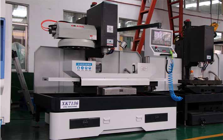
CNC milling machine
The introduction of computerized numerical control (CNC) has exponentially expanded applications of industrial machines by programmable automation of production and achieving impossible movements performed manually. such as circles, diagonal lines and other figures complicated that enable the manufacture of parts with highly complex profiles. Dit vertaalt zich ook in de optimalisatie van veel essentiële variabelen van elk productieproces: productiviteit, precisie, veiligheid, snelheid, herhaalbaarheid, flexibiliteit en vermindering van verspilling.
De veelheid aan freesmachines die vandaag de dag bestaan, heeft zich comfortabel uitgebreid tot de proliferatie van hun CNC-uitgeruste collega's. In werkelijkheid, Er zijn ook speciale kits om oude freesmachines om te bouwen tot een CNC-freesmachine.
In principe, de CNC-freesmachines lijken sterk op de conventionele en hebben dezelfde bewegende delen, dat is, de tafel, de snijkop, de spil en de zij- en dwarssledewagens. Echter, ze hebben geen hendels of krukken om deze bewegende delen te bedienen, maar eerder een scherm in een paneel vol bedieningselementen en een metalen doos waarin de elektrische en elektronische componenten zijn ondergebracht die de werking regelen van motoren die bestemd zijn om hetzelfde werk uit te voeren als zij. de hendels en krukken van de oude machines. Een van deze componenten is de CNC, dit is een computer die voornamelijk verantwoordelijk is voor de bewegingen van de freesmachine via de bijbehorende software. De combinatie van elektronica en aandrijfmotoren of servomotoren is in staat alle mogelijke freesbewerkingen te realiseren.
CNC-bewerking van portaalfreesmachines
De bewegingscontrole van de CNC begrijpen, we gaan kort bekijken hoe een conventionele freesmachine werkt.
De figuur schematiseert een typische freesmachine. Bij dit type machine, the cranks actuate the moving parts manually so that the cutting tool (milling cutter) moves linearly in at least three axes, which are called main axes:
X axis: horizontal and parallel to the clamping surface of the part. It is associated with the movement in the longitudinal horizontal plane of the milling table.
en as: forms a direct direction trihedron with the X and Z axes. It is associated with the movement in the horizontal transverse plane of the milling table.
Z axis: where the cutter is mounted, it is the one that has the cutting power and can adopt different positions according to the possibilities of the head. It is associated with the vertical displacement of the machine head.
If the milling machine has a fixed table, these three movements are executed by the spindle.
Echter, het is duidelijk dat het frezen van complexere onderdelen een groter aantal assen zal vereisen waarvan het traject niet alleen lineair is, maar ook roterend. Op dit punt komt het concept van CNC in het spel, waardoor een veelheid aan complementaire assen ontstaat die onafhankelijk worden bestuurd en worden bepaald door de beweging van draaitafels en / of verstelbare koppen. Dit geeft aanleiding tot een verscheidenheid aan machinemodellen die de bewerking van het onderdeel met verschillende vlakken en benaderingshoeken mogelijk maken.
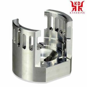
CNC machining cavity of milling machine
In de volgende afbeelding zien we een voorbeeld van een CNC-freesmachine met zijn basiscomponenten en hoofdonderdelen (X, Y, Z) en complementair (B, W) bijlen.
1 – Kolom
2 – Werkstuk
3 – Freestafel, met beweging in de X- en Y-as
4 – Strawberry
5 – Snijkop inclusief spindelmotor
6 – CNC-bedieningspaneel
7 – Koelvloeistof slangen
X, Y, Z – Main axes of displacement
B – Complementary axis of rotary displacement of the cutting head
W – Complementary axis of longitudinal displacement of the cutting head
The main function of the CNC is to control the movements of the table, the transverse and longitudinal carriages and / or the spindle along their respective axes by means of numerical data. Echter, this is not all, because the control of these movements to achieve the desired final result requires the perfect adjustment and the correct synchronization between different devices and systems that are part of every CNC process. These include the main and complementary axes, the transmission system, the workpiece clamping systems and the tool changers, each of which presents its modalities and variables that must also be properly stipulated.
This rigorous control is carried out by software that is supplied with the milling machine and is based on one of the CNC numerical programming languages, such as ISO, HEIDENHAIN, Fagor, Fanuc, SINUMERIK and Siemens. This software contains numbers, letters and other symbols – Bijvoorbeeld, the G and M codes – that are encoded in an appropriate format to define an instruction program capable of carrying out a specific task. G codes are machine motion functions (rapid moves, feeds, radial feeds, pauses, cycles), while M codes are miscellaneous functions that are required for machining parts, but are not machine motion. (spindle start and stop, tool change, coolant, program stop, enz.). From this it follows that to operate and program this type of machine requires basic knowledge in machining operations on conventional equipment, elementary knowledge of mathematics, technical drawing and handling of measuring instruments.
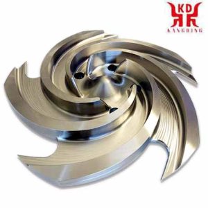
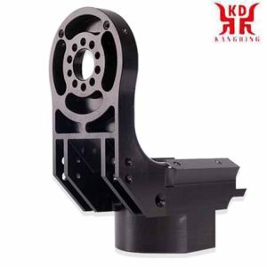
Milling impeller processing of milling machine
Currently the use of CAD (computer-aided design) and CAM (computer-aided manufacturing) programs is an almost mandatory complement to any CNC machine, therefore. Over het algemeen, the manufacture of a part involves the combination of three types of software:
CAD: makes the design of the part.
CAM: calculates the displacements of the axes for the machining of the part and adds the feed rates, rotation speeds and different cutting tools.
Control software (included with the machine): receives the instructions from the CAM and executes the orders to move the moving parts of the milling machine in accordance with these instructions.
The following video illustrates the manufacture of a part using CAD / CAM:
CNC milling machines are specially adapted for milling profiles, cavities, surface contours and die cutting operations, in which two or three axes of the milling table must be controlled simultaneously. Although, depending on the complexity of the machine and the programming carried out, CNC milling machines can operate automatically, an operator is usually required to change the cutters, as well as to mount and dismount the workpieces.
Industries that routinely use CNC milling machines include automotive (design of engine blocks, mallen, and miscellaneous components), ruimtevaart (aircraft turbines), and electronics (mold and prototyping), as well as manufacturing of machinery, instruments and electrical components.
Let’s see in this video some types of CNC milling machines, as well as working examples.