 English
 العربية
 中文(漢字)
 Čeština
 Dansk
Dansk Nederlands
 Suomi
Suomi Français
 Deutsch
 Italiano
 日本語
日本語 ಕನ್ನಡ
ಕನ್ನಡ 한국어
한국어 Português
 Русский
 Slovenčina
 Español
 Svenska
 Türkçe
CAXA draadsnijden is een softwaresysteem voor het CNC-programmeren van draadsnijmachines, die in mijn land een breed scala aan toepassingen kent op het gebied van draadsnijverwerking. Het kan snel bieden, efficiënt, en hoogwaardige CNC-programmeercodes voor diverse draadsnijwerktuigmachines, waardoor het werk van CNC-programmeurs aanzienlijk wordt vereenvoudigd. CAXA draadsnijden kan taken die moeilijk uit te voeren zijn onder traditionele programmeermethoden snel en nauwkeurig uitvoeren. It can provide you with automatic programming tools for wire-cutting machine tools, allowing the operator to interactively draw the graphics to be cut, and generate two-axis cutting traces with complex contours. CAXA wire cutting supports fast-moving wire cutting machine tools, and can output 3B, 4B and ISO format wire cutting processing programs. The process of automated programming is generally: Use the CAD function of CAXA wire cutting to draw processing graphics → Generate machining track and machining simulation → Generate wire cutting program → Transfer the WEDM program to the WEDM machine tool.
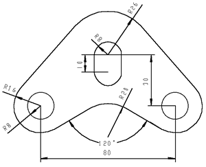
The following takes the processing of a convex-concave mold part as an example to illustrate its operation process. The dimensions of the convex and concave mold are shown in Figure 1. The wire-cutting electrode wire is a molybdenum wire of φ0.1mm, and the single-sided discharge gap is 0.01mm.
CNC machining automatic programming
Figuur 1, Design and processing of convex and concave mold size
1> Draw workpiece drawings
1.Draw a circle
(1) Select the “Basic Curve-Circle” menu item and use the “Center-Radius” method to make a circle;
(2) Enter (0, 0) to determine the center position of the circle, and then enter the radius value “8” to draw a circle;
(3) Don’t end the command, enter “26” when the system still prompts “Enter a point or radius on the arc”, draw a larger circle, and click the right mouse button to end the command;
(4) Continue to use the above command to make a circle, enter the center point (-40, -30), enter the radius values 8 En 16, respectievelijk, to draw another group of concentric circles.
2. Draw a straight line
(1) Select the “Basic Curve-Straight Line” menu item, select the “Two-point line” method, and the system prompts to enter the “first point (tangent point, vertical foot point)” position;
(2) Click the space bar to activate the feature point capture menu, and select “tangent point” from it;
(3) Click on the appropriate position of the R16 circle, and move the mouse at this time to see that the cursor draws an imaginary line. Momenteel, the system prompts to enter “the second point (tangent point, vertical foot point)”;
(4) Click the space bar again to activate the feature point capture menu, and select “tangent point” from it;
(5) Then determine the tangent point at the appropriate position of the R26 circle, and then the outer common tangent of the two circles can be easily obtained;
(6) Select “Basic curve-straight line”, click the “two-point line” sign, and switch to the “angle line” method;
(7) Click the drop-down mark after the second parameter, and select “X-axis angle” in the pop-up menu;
(8) Click the sign of “angle=45” and enter the new angle value “30”;
(9) Use the method used before to select the “tangent point” and click on the appropriate position at the bottom right of the R16 circle;
(10) After dragging the imaginary line to an appropriate position, click the left button of the mouse to complete the line drawing.
3. Make symmetrical graphics
(1) Select the “Basic Curve-Straight Line” menu item, select “Two-point Line”, and switch to the “Orthogonal” mode;
(2) Enter (0, 0), drag the mouse to draw a vertical line;
(3) Select the “Curve Edit-Mirror” menu item in the drop-down menu, and use the default “select axis” En “copy” methods. Momenteel, the system prompts to pick up the elements, and respectively click the two straight lines just generated and the concentric circles with radii 8 En 16 at the bottom left of the graph. Click the right mouse button to confirm;
(4) Momenteel, the system prompts to pick up the axis again, pick up the lead vertical line just drawn, and after confirming, a symmetrical figure can be obtained.
4. Long round hole
(1) Select the “Curve Edit-Translation” menu item, and select the “given offset”, “copy” En “orthogonal” methods;
(2) The system prompts to pick up the element, click the circle of R8, and click the right mouse button to confirm;
(3) The system prompts “X and Y direction offset or position point”, input (0, -10), it means that the X-axis displacement is 0 and the Y-axis displacement is -10;
(4) Use the above-mentioned method of making common tangents to generate the two vertical lines in the figure.
5. Final edit
(1) Select the rubber head icon, the system prompts “Pick up geometric elements”;
(2) Tap the plumb line and delete this line;
(3) Select the “Curve Edit-Transition” menu item, select the “Round Corner” En “Cut” methods, and enter the “Radius” value of 20;
(4) Follow the prompts to take two diagonal lines with an angle of 30° with the X axis to obtain the required arc transition;
(5) Select the “Curve Edit-Crop” menu item, select the “Quick Crop” method, the system prompts “Pick the curve to be cropped”, and pay attention to the segment to be cut;
(6) Use the left mouse button to click on the non-existent line segments to delete them and complete the graph.
2>Trajectory generation and processing simulation
1. Trajectory generation
The trajectory generation is based on the contours that have been constructed, combined with the wire cutting processing technology, given the determined processing methods and processing conditions, and the computer automatically calculates the processing trajectory process. The following will introduce the method of wire-cutting wire-cutting trajectory generation with this example.
(1) Select the “Track Generation” item, and in the pop-up dialog box, determine the processing parameters according to the default values.
(2) In this example, there is an offset between the processing track and the figure outline. When processing the concave die hole, the wire processing track is offset to the original pattern track for “gap compensation”. When processing the convex mold, the wire electrode processing track is offset outside the original pattern track for “gap compensation”. The compensation distance is ΔR=d/2+Z=0.06mm, zoals te zien in figuur 2. Enter this value into “first processing amount”, and then press OK.
Figuur 2. Actual processing track
(3) The system prompts “Pick Contour”. This example is a concave-convex mold. Not only the outer surface but also the inner surface must be cut. Here, the concave mold hole is cut first. In this example, there are three concave mold-shaped holes. Take the circular hole on the left as an example, and pick the contour. Momenteel, the R8mm contour line turns into a red dashed line, and a pair of bidirectional green arrows appear along the contour line at the position clicked by the mouse, and the system prompts “select chain picking direction” (the system defaults to chain picking).
(4) After selecting the clockwise direction, a pair of green arrows will appear in the direction of the vertical contour line, and the system will prompt “Select the side to be cut”.
(5) Because the picked contour is a concave mold hole, pick the arrow pointing to the inside of the contour, and the system prompts “input threading point position”.
(6) Press the space bar to activate the feature point capture menu, select “center of circle” from it, and then select on the R8mm circle. Dat is, it is determined that the center of the circle is the threading point position, and the system prompts “enter the exit point (“Enter” will coincide with the threading point)”.
(7) Click the right mouse button or press Enter, the system calculates the processing track of the concave model hole contour.
(8) Momenteel, the system prompts to continue to “pick contour”, and complete the processing tracks of the other two concave molds according to the above method.
(9) The system prompts to continue “pick contour”.
(10) Pick up section AB, at this time section AB becomes a red dashed line.
(11) The system prompts “select chain picking direction”, “select cutting side”, “input threading point position” En “input exit point” in sequence. Select the order processing of A—B—C—D—E—F—G—H—A, and point B is the starting point of the sequence. This contour is the outer surface. Select the outer side of the processing, adjust the threading point to outside the mold base, take the point as P (-29.500, -48.178), and select this point as the exit point.
(12) a single right-end track or ESC to generate, edit track selection command “track jump” feature to connect the tracks in the preceding paragraphs.