 English
 العربية
 中文(漢字)
 Čeština
 Dansk
Dansk Nederlands
 Suomi
Suomi Français
 Deutsch
 Italiano
 日本語
日本語 ಕನ್ನಡ
ಕನ್ನಡ 한국어
한국어 Português
 Русский
 Slovenčina
 Español
 Svenska
 Türkçe
5-asbewerking van basisonderdelen
Het krachtige 5-assige CNC-freesbewerkingscentrum, het CNC-systeem beschikt over de ruimtecoördinatensysteemrotatie en de schuine gereedschapscompensatiefunctie, wat de mogelijkheid biedt voor de bewerking van sommige onderdelen die bewerking van hellende oppervlakken en een hoge bewerkingsnauwkeurigheid vereisen. Bij bewerking op een hellend vlak, het is moeilijk om een bewerkingsprogramma samen te stellen omdat het coördinatensysteem in de ruimte verandert. Noodzaak om de conventionele programmeer-denkmodus voor programmeren te doorbreken, en speciale verwerking van het programma. This article discusses this issue in conjunction with the actual processing of model products.
Such parts are often encountered in the production process of products, and they need to be punched, bored, and milled on the inclined surface. Or it needs to be processed on several inclined surfaces with different directions and different slopes in the same clamping, en elk hellend oppervlak heeft een hogere geometrische tolerantievereiste. The conventional method of processing such parts is to pull the head of the bed, draai het werkblad of gebruik een modulair armatuur. Als de verwerkingsrichting of verwerkingspositie anders is, een tweede klemming en heruitlijning zijn vereist, en het verwerkingsproces is uiterst omslachtig. Vanwege de beperking van de klempositionering en de werktuigmachine zelf, de bewerkingsnauwkeurigheid van de onderdelen kan niet worden gegarandeerd. Bijvoorbeeld, in the T×× table body processing, there are many holes on the inclined surface, en het speciaal gevormde oppervlak is niet gemakkelijk vast te klemmen, the positioning reference is not good, and the error accumulation caused by multiple clamping, sometimes the hole margin error exceeds 1mm.
In order to solve the processing problem of this kind of parts, door voortdurende verkenning en voortdurende verbetering van procesmethoden, combined with the factory’s existing machine tools, a five-axis CNC milling machining center was selected to solve this problem. De geselecteerde werktuigmachine is een 5-assige koppeling. In addition to 3 lineaire assen, het heeft ook twee roterende assen (C-as: -360°~360°) en zwenkkop (B-as: 0°~110°). The control system used is FANUC160i, which has the functions of space coordinate system rotation and inclined tool compensation.
From the perspective of realizing bevel processing, multiple bevels in different directions and different angles can be punched, saai, tapped, milled and other processes can be completed after one clamping. Reduce the number of clamping times, reduce labor intensity, shorten the production cycle of the product, en nog belangrijker, improve the processing accuracy of the parts and ensure the consistency of product quality.
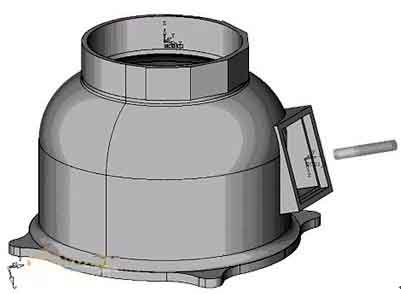
Take the processing of a certain base part as an example. The parts are shown below: To process this base, het is duidelijk dat de werktuigmachine een 2-assige koppelingsinterpolatie op de XZ- en YZ-vlakken en een spilkopzwaaibeweging moet voltooien. Omdat om het gereedschap loodrecht op het bewerkte oppervlak te maken, de spil moet een kopzwaaibeweging maken. Having a rotating head involves a series of multi-axis machining issues such as pendulum length. Daarom, it is necessary to use multi-axis programming means to complete. Programming and machine tool debugging are difficult, which puts higher demands on programmers and machine operators. Bij praktische toepassingen, rekening houdend met factoren zoals het garanderen van de veiligheid van de werktuigmachine, it is necessary to simulate the processing process and perform multiple air cuts to ensure that the program is correct before formal processing can be performed. In aanvulling, het meerassige programma-algoritme is behoorlijk ingewikkeld, en er moet rekening worden gehouden met de invloed van factoren zoals de slingerlengte. Er moet voor een bepaalde werktuigmachine een specifieke nabewerking plaatsvinden, but the post-processing is often due to the difference in algorithms and control positions, as well as the influence of calculation stability. Het programma dat wordt verkregen via softwarematige nabewerking is vaak moeilijk om te voldoen aan de eisen van de nauwkeurigheid van onderdeeltekeningen in termen van besturingsnauwkeurigheid.
The analysis shows that the direct cause of the increase in programming difficulty is the appearance of the inclined plane. Daarom, als het bewerkingsvlak samen kan vallen met het hellende vlak, dan zal dit soort probleem worden omgezet in een semi-verwerkingsprogrammeringsprobleem met twee assen, en de programmeerproblemen zullen aanzienlijk worden verminderd. Daarom, it is conceivable to use the coordinate system conversion function of the machine tool (G68-opdracht) om het bewerkingsvlak te laten samenvallen met het hellende vlak. The second tool length compensation command (G432) is used to add the tool length in the vertical direction of the inclined plane. Na bovenstaande verwerking, het probleem van schuine verwerking wordt omgezet in vlakverwerking om op te lossen, thus the programming difficulty is greatly reduced. Als u meerdere hellende vlakken tegelijkertijd moet bewerken, je hoeft alleen maar de C-as naar C0 te draaien (de nulpositie van de werktafel, de richting van de nulpositie is hetzelfde als de zwenkrichting van de spil), en realiseer vervolgens de verwerking door het coördinatensysteem te roteren en de gereedschapslengte te vergroten. Als de verwerkingsvorm relatief eenvoudig is, programming can be done manually. This makes it possible to realize the machining of multiple inclined surfaces, multiple positions, en meerdere gereedschapswissels in één enkele opspanning van de CNC-bewerkingsmachine.
The program structure is as follows:
%
N0100O0008 (program name)
N0102M6T1; (tool change)
N0104G0G90G56X400Y200Z260B0C0; (Move to the reference point)
N0106G432X200Z150H1Bω; (add the knife length in the direction perpendicular to the inclined plane)
N0108M3S3000; (Spindle forward rotation)
N0110M8; (open cutting fluid)
N0112G68X188Y0Z60I0J1K0Rω; (Coordinate system conversion, ω is the angle of rotation of the main shaft from zero to perpendicular to the inclined plane)
……
N0200G69; (cancel coordinate system rotation)
N0202G492X200Z300; (Slope tool compensation canceled, move to a safe position)
N0204M9; (cutting fluid off)
N0206Cα; (C axis rotation, α is the minimum angle between the vertical line of the nth inclined plane to be processed and the C0 position)
N0208G0G90G56X400Y200Z260B0C0; (Move to the reference point)
N0210G432X200Z150H1Bωn; (add the knife length in the direction perpendicular to the inclined plane)
N0212G68X188Y0Z60I0J1K0Rωn; (Coordinate system conversion, ωn is the angle of rotation when the main shaft turns from zero to perpendicular to the slope)
…
N0200G69; (cancel coordinate system rotation)
N0202G492X200Z300; (Slope tool compensation canceled, move to a safe position)
N0204M9; (cutting fluid off)
N0204M30; (program ends, return to program head)
Although the bevel machining has been achieved in the above discussion, it is limited to drilling, saai, tikken, and milling on the bevel. The simple shapes composed of straight lines and arcs are limited to manual programming. If the milling shape is more complicated. Such as milling equation curves, three-dimensional curved surfaces, and lettering on an inclined plane, how to program it?
Even when these similar shapes are processed on a flat surface, manual programming is not possible, and it can only be completed by CAM software. Through careful study of machine tools and CAM software, a set of software programming combined with manual programming was found to be an effective way to complete the processing and programming of such parts.
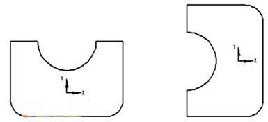
The analysis shows that in ordinary three-axis milling programming, the direction of the tool axis is always perpendicular to the XOY plane. But when the spindle deviates from the original vertical direction and the tool plane is inclined, how can the program generated on the XOY plane run correctly on the inclined plane? The analysis shows that although the coordinate system has been rotated, if the relative position of the figure (A) in the original coordinate system and the shape to be processed on the inclined plane (B) and the relative position in the new coordinate system are kept consistent on the XOY plane . Then the program generated on the XOY plane can be directly applied to bevel machining.
According to the influence of the swing head movement of the machine tool on the graphics position, the analysis shows that when drawing on the XOY plane, the graphics should be rotated 90° counterclockwise with the programming origin as the rotation center (the rotation angle should be determined according to the specific conditions of the machine tool). Op deze manier, the graphic position in the CAM software is kept consistent with the actual machining position. By adding and modifying the program head and program end, dat is, adding coordinate system conversion and inclined tool compensation, software programming and manual programming are combined. This realizes the machining of arbitrary complex shapes such as milling equation curves, three-dimensional curved surfaces, and lettering on the inclined surface.
5-axis milling equation curve on inclined plane, three-dimensional surface
Through the actual machining verification, it is confirmed that the method is within the allowable range of the machine function and stroke, and the programming of this method can realize the machining programming of any complicated shape on any inclined plane.
The following figure shows an example of processing a three-dimensional curved surface on a 52° inclined plane:
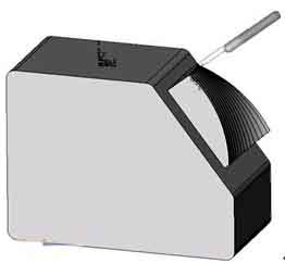
Machining three-dimensional curved surface