 English
 العربية
 中文(漢字)
 Čeština
 Dansk
Dansk Nederlands
 Suomi
Suomi Français
 Deutsch
 Italiano
 日本語
日本語 ಕನ್ನಡ
ಕನ್ನಡ 한국어
한국어 Português
 Русский
 Slovenčina
 Español
 Svenska
 Türkçe
가공 부품 도면의 치수: 표준 공차 및 기본 편차, 표면 거칠기, 정확성, 평탄, 위치, 병행, 동축성, 등.
| 모양 및 위치 공차 | 직위 정도 | 병행 | 동심도 | 수직성 | 전체 점프 정확도 | 대칭 | 평탄 | 원통형 | 진원도 | 거칠기 |
| 상징 | ||||||||||
| 측정 정확도 | 0.001 | 0.001 | 0.001 | 0.001 | 0.001 | 0.001 | 0.001 | 0.001 | 0.001 | Ra0.01 |
| 가공 정확도 | 0.03 | 0.005 | 0.005 | 0.01 | 0.01 | 0.01 | 0.002 | 0.01 | 0.005 | Ra0.04 |
Symbol of surface roughness of parts
The concept of part surface roughness
부품 표면에 작은 간격으로 봉우리와 골이 있습니다., 이에 의해 형성된 미세 기하학적 특성을 표면 거칠기라고 합니다.. CNC 가공 부품의 경우, CNC 절단 및 분할 시 부품 표면에 공구에 의해 남겨진 공구 자국과 표면 금속의 소성 변형으로 인해 형성됩니다..
The surface roughness of parts is also a technical index for evaluating the surface quality of parts. It has an impact on the matching properties, working accuracy, 내마모성, 내식성, sealing, appearance, 등. of the parts.
The code, symbol and mark of surface roughness
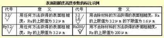
GB/T 131-1993 specifies the surface roughness code and its notation. 부품의 표면 거칠기를 나타내는 도면의 기호는 아래 표와 같습니다..
부품의 표면 거칠기 평가 변수는 다음과 같습니다.:
1) 윤곽선의 산술 평균 편차 (라)
샘플링 길이 이내, 윤곽 오프셋 절대값의 산술 평균. Ra 값과 샘플링 길이 l. 표 보기.
2) 최대 프로필 높이 (Rz)
샘플링 길이 내에서 등고선 피크의 상단선과 등고선 피크의 하단선 사이의 거리.
비고: Ra 매개변수를 사용할 때 선호됩니다..
표면 거칠기에 대한 표시 요구 사항
1) 표면 거칠기 코드 라벨링의 예
표면 거칠기 높이 매개변수 Ra, Rz, Ry는 코드에 숫자 값으로 표시되어 있습니다., 단, 매개변수 코드 Ra는 생략될 수 있습니다.. The other parameters need to be marked with the corresponding parameter code Rz or Ry before the parameter value. See the table for labeling examples.
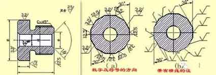
2) The method of marking the numbers and symbols in the surface roughness of the surface roughness
Marking method of surface roughness symbols on drawings
1) The surface roughness code (상징) should generally be noted on the visible contour line, the size boundary line or their extension line, and the tip of the symbol must point to the surface from the outside of the material.
2) The direction of the numbers and symbols in the surface roughness code must be marked as required.
2) 최대 프로필 높이 (Rz)
샘플링 길이 내에서 등고선 피크의 상단선과 등고선 피크의 하단선 사이의 거리.
비고: Ra 매개변수를 사용할 때 선호됩니다..
표면 거칠기에 대한 표시 요구 사항
1) 표면 거칠기 코드 라벨링의 예
표면 거칠기 높이 매개변수 Ra, Rz, Ry는 코드에 숫자 값으로 표시되어 있습니다., 단, 매개변수 코드 Ra는 생략될 수 있습니다.. The other parameters need to be marked with the corresponding parameter code Rz or Ry before the parameter value. See the table for labeling examples.
2) The method of marking the numbers and symbols in the surface roughness of the surface roughness
Marking method of surface roughness symbols on drawings
1) The surface roughness code (상징) should generally be noted on the visible contour line, the size boundary line or their extension line, and the tip of the symbol must point to the surface from the outside of the material.
2) The direction of the numbers and symbols in the surface roughness code must be marked as required.
Labeling example of surface roughness
On the same drawing, each surface is generally marked with a code (상징) only once, and as close to the relevant dimension line as possible. When the space is narrow or it is inconvenient to label, it can lead to the label. When all the surfaces of the parts have the same surface roughness requirements, they can be uniformly marked on the upper right corner of the drawing. When most of the surfaces of the parts have the same surface roughness requirements, the most used code (상징) can be marked on the upper right corner of the drawing at the same time, and the word “the rest” shall be added. The height of the uniformly marked surface roughness code (상징) and explanatory text should be 1.4 times that of the drawing mark.
Continuous surfaces on parts, surfaces of repeated elements (such as holes, teeth, 그루브, 등.), and the same surface that is not continuous with thin solid lines. The surface roughness code (상징) number is only noted once.
When there are different surface roughness requirements on the same surface, thin solid lines should be used to draw the dividing line, and the corresponding surface roughness code and size should be noted.
When the tooth (tooth) shape is not drawn on the working surface of gears, 스레드, 등., the surface roughness code (상징) notation method.
The working surface of the center hole, the working surface of the keyway, the surface roughness code of the chamfer, and the rounded corner can be simplified and marked.
When the parts need to be partially heat-treated or partially plated (coated), thick dotted lines should be used to draw the range and mark the corresponding dimensions. It can also be written on the horizontal line of the long side of the surface roughness symbol.
Numbers and symbols in surface roughness
표준 공차 및 기본 편차
5. 표준 공차 및 기본 편차
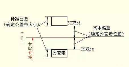
생산을 원활하게 하기 위해, 부품의 상호 교환성을 실현하고 다양한 사용 요구 사항을 충족합니다., 국가 표준 “한계 및 적합치” 공차 영역이 두 요소로 구성되어 있음을 규정합니다.: 표준 공차 및 기본 편차. 표준 공차는 공차 영역의 크기를 결정합니다., 기본 편차에 따라 공차 영역의 위치가 결정됩니다..
1) 표준 공차 (그것)
표준 공차 값은 기본 크기 및 공차 등급에 따라 결정됩니다.. 공차 수준은 크기의 정확성을 결정하는 표시입니다.. 표준 공차는 다음과 같이 나뉩니다. 20 레벨, 즉, IT01, IT0, IT1, …, IT18. IT01에서 IT18로 크기 정밀도가 감소합니다.. 표준 공차의 구체적인 값은 해당 표준에서 확인할 수 있습니다..
CNC 가공의 기본 편차
2) 기본편차
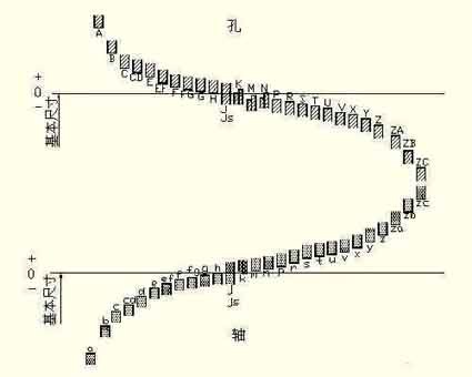
기본편차란 표준한계 및 조정에서 영점선의 위치에 대한 공차역의 상한 또는 하한 편차를 말합니다., 일반적으로 0선 근처의 편차를 나타냅니다.. 공차 영역이 영점선 위에 있을 때, 기본 편차는 가장 낮은 편차입니다.; 반대로, 상한 편차입니다. 건초 28 총 기본 편차, 코드명은 라틴 문자로 표시됩니다., 대문자를 구멍으로, 소문자를 축으로 사용.
It can be seen from the basic deviation series diagram:
The basic deviation A~H of the hole and the basic deviation k~zc of the shaft are the lower deviation; The basic deviation K~ZC of the hole and the basic deviation a~h of the shaft are the upper deviation; The tolerance zones of JS and js are symmetrically distributed on both sides of the zero line, and the upper and lower deviations of the hole and shaft are +IT/2 and -IT/2 respectively. The basic deviation series diagram only shows the position of the tolerance zone, not the size of the tolerance. 그러므로, one end of the tolerance zone is an opening, and the other end of the opening is defined by a standard tolerance.
The basic deviation and standard tolerance, 치수 공차의 정의에 따라, 다음 계산식을 가지고:
ES=EI+IT 또는 EI=ES-IT
ei=es-IT 또는 es=ei+IT
홀과 샤프트의 공차영역 코드는 기본편차 코드와 공차영역 등급코드로 구성됩니다..