 English
 العربية
 中文(漢字)
 Čeština
 Dansk
Dansk Nederlands
 Suomi
Suomi Français
 Deutsch
 Italiano
 日本語
日本語 ಕನ್ನಡ
ಕನ್ನಡ 한국어
한국어 Português
 Русский
 Slovenčina
 Español
 Svenska
 Türkçe
임펠러는 움직이는 블레이드가 장착된 휠 디스크를 말합니다.. 임펠러의 일반적인 재료에는 주철이 포함됩니다., 청동, 스테인레스 스틸, 망간 청동, 모넬, 인코넬, PPS 플라스틱과 같은 비금속 재료, 페놀수지 등. .
임펠러의 가공 요구사항:
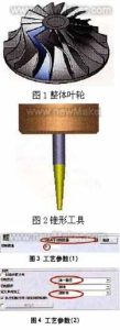
5-축 밀링 임펠러 형상
(1) 더 큰 에너지 헤드를 줄 수 있습니다.;
(2) 임펠러를 통과하는 가스의 손실이 적어야 함, 그건, 임펠러를 통과하는 가스의 효율이 높아야 함;
(3) 가스가 임펠러에서 흘러나올 때 매개변수가 적절합니다., 가스가 후속 고정 부품을 통과할 때 흐름 손실이 작도록;
(4) 임펠러 유형은 전체 기계 성능 곡선의 안정적인 작업 조건 영역과 고효율 영역을 넓힐 수 있습니다.. 그러므로, 임펠러 밀링은 5축 연결 기계 기술을 채택해야 합니다..
단계 1: 블레이드 프로파일 밀링
블레이드 프로파일 밀링은 테이퍼 링 커터를 사용합니다. (직경 3mm, 절삭날 길이 30mm). 그림 참조 2. 단일 블레이드 유형 프로파일 밀링으로 특정 임펠러를 가공하기 위해 채택된 솔루션 2 곡선, and the milling range of the tool is controlled between the two curves. The choice of cutting type “depends on the amount of milling”, the cutting amount is controlled by the cutting amount to generate the cutting path, 그림과 같이 3.
The milling mode is “single path”, and the type of unidirectional addition is defined as “climb milling”. The above two parameters can be defined according to the process requirements, and the specific shape of the impeller should also be considered, 그림과 같이
Generate impeller blade surface code
1. Define the geometry
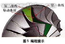
Select the outer edge of the impeller blade as the “first” curve, select the inner edge of the impeller blade as the “second” curve, and select the curved surface between the two blades as the “guide surface”. The above 3 items are required options and are the basic requirements for generating “암호”.
그만큼 “first” 곡선은 공간의 윤곽에 따라 곡면 처리 궤적을 제한합니다., 제한된 영역에서 궤적이 처리되도록 1;
그만큼 “second” 곡선은 공간의 윤곽에 따라 곡면 처리 궤적을 제한합니다., 제한된 영역에서 궤적이 처리되도록 2;
“안내면” 제품에 처리할 표면 개체를 정의합니다., 그림과 같이 5.
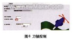
공구 축 벡터 제어 설정
2. 공구 축 제어 정의
공구축의 기울기 방법을 "밀링방향에 따른 기울기"로 정의. 가공을 위해 공구의 측면 모서리를 사용해야 하는 필요성을 고려, 이때 공구 축 벡터를 합리적으로 제어해야 합니다.. Milling 방향에 따라 Tilting 방식을 사용, 도구는 곡면 모양의 자연스러운 방향을 따라 도구 경로를 생성합니다., 이러한 도구 경로로 처리된 부품은 더 매끄러워집니다.. 그만큼 “밀링 방향의 측면 경사각” 85°로 설정되어 있습니다., which mainly takes into account the taper angle of the cutting tool (using the side edge of the milling cutter to process the curved surface of the space can greatly improve the finishing efficiency of the curved surface). 그림 참조 6.
Pay attention to the above value of 85°, which will make the machine tool rotate continuously. Observe the machine simulation. The rotation mentioned here is due to interference checking. When we use 80° or 85°, observe the tool change and the change of the machine in the machine simulation, and compare them. The tool taper angle is changed to 2.5°, and the settings are reset to compare the differences.
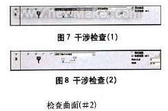
Interference inspection of milling impeller
3. Define interference check
Define the first interference check option: Select the leading surface as the interference check surface, and the system will automatically add the added surface as the interference check surface. The application of this situation is mainly to solve the phenomenon that the twisted guide surface interferes with the tool after being processed, 그림과 같이 7.
Define the second interference check option: Select the curved surface between the two impeller blades again as the second interference check surface. When the tool interferes, it will “retract along the direction of the tool axis”. The check surface refers to the interference surface of the tool when used for space curved surface processing, 그림과 같이 8.
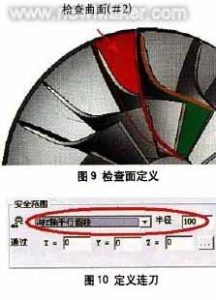
Continuous tool path for machining impeller blades
4. Define continuous tool path
Define the continuous tool path type as “cylinder parallel to Z axis” within the safety range. Since it passes through the X0, Y0, and ZO points and is parallel to the Z axis, the transition between the tool paths will be connected with a cylinder with a radius of 100mm, the axis passing through the 0 point and parallel to the 7 중심선. 그림 참조 10. Select “Use feed path macro command” in the first feed. In the last retraction point, select “Use retraction path macro”, enter the macro program type as “arc tangent”, and set the arc sweep to 45°. Through the above settings, you can further control the in and out of the tool path, 그림과 같이 11-14.
Tool feed path for roughing + 마무리 손질
The forward and backward tool paths have the same macro command settings, so the same results (the same for each layer) must be produced in the blade processing tool path, 그림과 같이 15.
단계 2: Processing the middle area of the blades of the two impellers
When milling the middle area of the blades of the two impellers, a ball-end cutter (직경 3mm) is used, and the curved surface path is “profiling milling between two curved surfaces”, 그림 참조 1. The cutting method is “Z-type milling”, and the cutting sequence is “from inside to outside”, 그림과 같이 2. The relative curved surfaces of the blades of the two impellers are defined as the “first” curved surface and the “second” curved surface, and the curved surface between the two blades is defined as the “driving curved surface”. 그림 참조 3.
1. 공구 축 제어 정의
The tool axis will “tilt through the curve”, 그림 참조 4. The curve approach type is “approach point”, and an “inclined curve” is established between the outer edges of the two blades, 그림과 같이 5. The method of establishing the curve is to use the auxiliary surface of the two impellers to establish an edge curve at the top. The curved surface processing trajectory is restricted by the contour of the space, 제한된 영역에서 궤적이 처리되도록, and then the trajectory range of the tool is controlled.
2. Define tool path interference check
Select the “cutting edge” of the tool to participate in the interference check, and also check the “guide surface” 그리고 “check surface”, 그림과 같이 6. Check that the surfaces are the inner surfaces of the two impeller blades (그건, 그만큼 “first” surface and “second” surface mentioned above). 물론, you must select the two surfaces again. When checking the ‘guide surface’ surface.
3. Define continuous tool path
Define the first feed path as “use feed path macro command”, and define the last tool retraction point as “use retract path macro command”, 그림과 같이 7. All slices are connected smoothly with the knife path using “mixed splines”, 그림과 같이 8. The feed macro program adopts “vertical tangential radius”, and the arc sweep is 10º, 그림과 같이 9. The trajectory of the infeed and outfeed generated in this way is similar to a straight line, as shown in Figure l0.
The third step: the control of the tool axis during the finishing process
Defining the space curve is a good way to control the tool axis, it can make the tool path you define is very smooth, and can greatly shorten the calculation time. 하지만, the definition of the space curve requires a very rich experience in actual machining, familiarity with CAD instructions and an understanding of the related functions of 5-axis aviation milling. The Cimatron system will automatically calculate the swing direction of the tool to avoid interference and collision.
Select the leading surface as the interference check surface, and define the tool path generation type, and the tolerance is set to 1.6. A margin of 0.1 is reserved here, which is the margin for processing during the final root removal, 그림과 같이 1.
In order to avoid the occurrence of improper processing, we make the tool path extend 10mm at the cutting/cutting place, so as to avoid this kind of situation. as shown in picture 2. Set the percentage value of the tool diameter to 10. The result of this procedure is shown in Figure 3.
단계 4: Tool path control based on roughing program on the basis of finishing
On the basis of finishing, we can easily use the blank layer to build the roughing program, first copy the last program. The roughing and milling settings are shown in Figure 4.
In the roughing tool path, the number of layers and spacing are respectively defined and then the number and spacing of the processing tool path are defined. The spacing here is the 3D distance between the two layers, here you can also define the finishing tool path.
Define the guiding surface in the surface path, cancel the original guiding surface, and select the new revolving surface just created. Click the “Advanced” option and select “Generate tool path on the front side”, 그림과 같이 5. If this option is not selected, the tool path will be generated in the entire impeller blade. This dialogue pivot can also be used to define the angle between the tool path and the surface.
수치 5, the angle setting between the cutting path and the curved surface
Calculate the program segment to get the rough machining + finishing tool path, 그림과 같이 6.
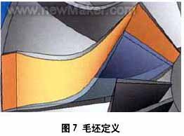
단계 5: Add blanks to optimize the rough tool path
Add blanks in each program segment to optimize the cutting path. Establish 3 curved surfaces between the impeller blades, and use these 3 surfaces to define the blank. The blade is shown in Figure 7.
Adjust the transparency of the blade so that it is convenient to observe the blank. When selecting, we can see that a lot of toolpath trajectories will be generated, 그림과 같이 8.
In addition to parts, there are many toolpaths that have not participated in cutting. Now through simple settings to cancel the path of these blanks. Copy the last program and edit it, open the “Rough Definition” option, and select the rough surface you just defined, 그림과 같이 9. 마지막으로, calculate the program to get the tool path trajectory. 그림과 같이 10.
If you see the tool path trajectory connected in space (after the blank is defined), it means that the blank you defined plays a certain role in the tool path calculation. If you are not satisfied with this connection method, you can change the corresponding parameters in “Continuous feed” until you get a satisfactory result.