 English
 العربية
 中文(漢字)
 Čeština
 Dansk
Dansk Nederlands
 Suomi
Suomi Français
 Deutsch
 Italiano
 日本語
日本語 ಕನ್ನಡ
ಕನ್ನಡ 한국어
한국어 Português
 Русский
 Slovenčina
 Español
 Svenska
 Türkçe
현대 산업에서는 부품의 복잡한 표면 디자인이 증가함에 따라, 5-축 가공은 CNC 가공의 증가하는 비율을 차지할 것입니다.. 5축 CNC 가공으로 2개의 회전 자유도가 추가됨, CNC 가공 동작 시뮬레이션 계산 및 공구 간섭 확인의 어려움이 증가합니다., 특히 매우 복잡한 형상의 부품을 가공할 때. 그러므로, in order to ensure that the five-axis CNC machine tool performs high-efficiency and high-quality milling processing, the development of five-axis machining tool path generation and interference checking software will become a major issue for researchers.
proposed a feature projection method suitable for five-axis CNC machining tool interference processing, which is to discretize the machined surface into a series of surface feature points. 도구 간섭 발생 여부는 특징점이 도구 표면 내부로 들어가는지 여부로 판단할 수 있습니다.. 동시에, the machined curved surface and the tool surface are projected onto a specific plane, and only the feature detection points in the curved surface area including the tool projection graphics are subjected to interference inspection, which improves the efficiency of interference detection.
1. 간섭 확인 방법
Coordinate system and coordinate transformation
Establishment of 5-axis coordinate system
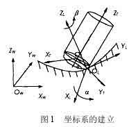
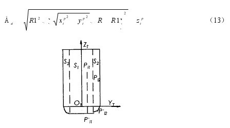
그림과 같이 1, the local coordinate system L for NC machining of five-axis circular cutter is represented as XL axis, YL axis and ZL axis. The YL axis always points to the cutting direction f of the tool contact (CC point for short) OL, and the ZL axis points to the normal direction outside the surface n. The XL axis is determined by the right-hand rule of the YL axis and ZL axis. The tool generally rotates around the XL axis from the ZL axis to the YL axis by a lead angle (heel angle) a, and rotates around the ZL axis one by one slip angle b. 게다가, 도구 좌표계 T (XT, YT, ZT) 도구 위치 지점에서도 정의할 수 있습니다. (줄여서 CL포인트) 구약. Wherein YT axis pointing point and CC-dot chain line CL direction, ZT axis direction of tool axis vector, XT axis direction is determined by the right hand rule and YT ZT axis of the shaft. The coordinate origin is at the tool center point (즉, CL 포인트) 구약. 간섭검사를 단순화하기 위해, 상대적으로 규칙적인 모양의 도구 표면은 간섭 검사의 기준으로 사용됩니다.. The processed surface is discretized to express the surface shape in the form of a set of characteristic points. 이러한 특징점의 원본 데이터는 세계 좌표계 W로 표현됩니다., 따라서 특징점 데이터는 먼저 세계 좌표계 W에서 변환되어야 합니다. (OW-XW, 이다, ZW) 로컬 좌표계 L로 (OL~XL, YL, ZL) ). 그런 다음 로컬 좌표계 L에서 공구 좌표계 T로 변환됩니다. (OT-XT, YT, ZT).
Interference inspection method for 5-axis ring cutter machining
간섭 확인 방법
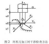
공구와 파워 헤드를 선택한 경우, 도구 시스템의 크기 (도구 및 전원 헤드) 알려져 있다. Whether the tool system interferes with the machined surface can be determined by judging whether the feature point P enters the tool surface. 그림과 같이 2, 링 나이프를 가공할 때 공구 시스템과 가공 표면 사이의 위치 관계입니다.. 공구 좌표계에서, 특징점 P의 좌표를 PI라 하자 (Xpt, 넵, Zpt). 도구 시스템의 다양한 조합 부분에 따르면, 특징점 P의 좌표값 Zpt는 4 판단을 위한 부분. 세부사항은 다음과 같습니다:
특징점 P가 u1 범위 내에 있을 때, 간섭이 발생하지 않습니다.
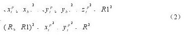
특성점 P가 u2의 범위에 있을 때, 두 가지 상황이 있어요, the torus is divided into two parts: the small cylindrical part P1 and the circular part P2. 원통형 부분 P1에 특징점이 포함된 경우, 도구 간섭이 발생합니다, 그건,
여기서 R은 공구의 반경을 나타냅니다., R1은 원형 공구 링의 반경을 나타냅니다..
링 부분 P2에 특징점이 포함된 경우, 도구 간섭도 발생, 만족하는 것
5 axis milling tool interference calculation formula
스타일에
5-axis machining interference calculation formula
If the feature point P does not enter the P1 and P2 parts, 도구 간섭이 발생하지 않습니다..
특성점 P가 u3의 범위 내에 있을 때, 특성점 P와 ZT축 사이의 거리가 공구 반경보다 작은 경우, 도구 간섭이 발생합니다, 만족하는 것
그렇지 않으면, 도구 간섭이 발생하지 않습니다..
When the feature point P is in the range of u4, 상황은 그 때와 똑같다. 3, as long as the tool radius R in equation (3) is replaced by the power head radius d/2 to make the judgment.
The feature points of the curved surface that interfere with the tool system are called interference points. Detect all the interference points according to the above method, and calculate the amount of interference in the radial direction of each interference point, and then use an appropriate method to eliminate the interference.
Feature Projection Method for Interference Inspection
Project the tool system and the feature points of the curved surface onto a two-dimensional plane (projection plane), and divide the machined surface into a series of squares by taking a reasonable distance on the two-dimensional projection plane. 그림과 같이 3, when the square is completely covered by the contour of the projected tool system, it is recorded as a complete square. The surface feature points in this area may interfere with the tool system;
When the square is not intersected by the contour of the projected tool system at all, it is recorded as a non-square and it is impossible to interfere with the tool system;
When the square part is covered by the contour of the projected tool system, it is recorded as a partial square. In order to further reduce the number of feature points inspection, a quadtree segmentation process is performed on part of the squares, non-squares are deleted, and the feature points that may interfere with each other are re-edited in the order of regions, and then the coordinate transformation and interference inspection are performed.
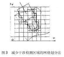
Net division method for reducing interference detection area in NC machining
2. Interference elimination method:
Rotating tool axis
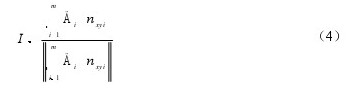
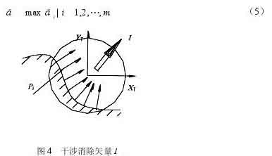
At a tool location point, there are m surface feature points that interfere with the tool system. Considering the interference situation of m interference points comprehensively, an optimal direction to eliminate interference can be found to eliminate the interference of the tool most effectively. 이러한 이유로, a new concept of “interference cancellation plane” is introduced. Project the surface normal vectors at m interference points onto the XTYT plane of the tool coordinate system T. Suppose the projection of the surface normal vector at the interference point on the XTYT plane is nxyi (i=1, 2, …, 중), and the interference component of the interference point on the XTYT plane is Dt (i=1, 2, …, 중) . 그림과 같이 4, the interference cancellation vector I can be obtained by
Interference detection method of rotating tool axis
After the interference cancellation vector I (Sx, Sy, Sz) is calculated from the formula (4), the interference cancellation vector I and the ZT axis form the interference cancellation plane. Let the cross product vector of the axis ZT and the elimination vector I be K. On a plane parallel to the “interference elimination plane”, the interference elimination angle d that calculates how much the tool is inclined around the K axis I can just eliminate the tool interference. 그림과 같이 5. Assuming that the interference point Pi (i=1, 2,…, 중) is excluded from the surface of the tool system, the minimum angle required is di (i=1, 2,…, 중). Then the interference cancellation angle d is the maximum value of all angles di
Interference cancellation vector method
To exclude the interference point Pi from the tool system, the interference point Pi is fixed, and the tool system rotates around the K axis in the I direction. It is equivalent to the angle of rotation di of the interference point Pi relative to the tool system and the tool coordinate system in the plane of the parallel interference elimination plane IOTZT. Take the ring knife as an example to analyze.
그림과 같이 5, the rotation axis of the tool system passes through the center point O1 of the arc of intersection of the elimination plane IOTZT and the toroidal surface of the tool, and is parallel to the vector K, passes the interference point Pi, and is parallel to the elimination plane IOTZT. As a section plane, the intersection line between the section plane and the torus of the tool is a quartic curve, and the intersection line with the cylindrical surface is two straight lines. There are two situations in which the axis of the ring knife rotates. When the interference point Pi falls into the circular knife cylinder, the rotation angle di is ∠PiOPi’ (Figure 5a), and the calculation formula is
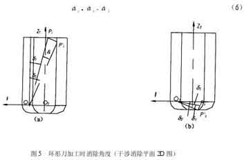
Eliminate interference angle during ring cutter processing
and the angle d1 is calculated as follows
그때에, the point Pi intersects the cylindrical surface section line during the rotation, and the calculation formula for d2 is
When the point Pi does not intersect the cylindrical section line during the rotation, the point Pi’ may intersect the quartic curve of the circular section or the section line of the bottom plane of the tool. The calculation of the angle d2 is more complicated when it intersects the quartic curve of the circular section. In order to simplify the calculation, the rotation angle is treated conservatively. 이때, the calculated angle d2 is larger than the actual angle, but it has no effect on the tool interference processing. The conservative processing points Pi’ are all rotated to intersect the bottom plane of the tool, and the angle d2 is equal to
그림과 같이 5(b), when the interference point Pi falls into the circular knife ring, the rotation angle is also conservatively treated. The points Pi’ are all rotated to intersect the bottom plane of the tool, the rotation angle di is ∠PiOPi’, and the calculation formula is the same as equation (6), where the angles d1 and d2 are calculated as follows
When raising the knife, the interference point intersects the arc surface of the knife edge
When the denominator in formula (11) is smaller than the numerator, the point Pi’ cannot intersect the bottom plane of the tool during the rotation. 이때, the interference cannot be eliminated by rotating the tool axis, but the possibility of this situation is extremely small.
The same principle can handle the interference points in the cylinder of the power head.
Although the tool system can eliminate the interference points by rotating the d angle to the I direction, the tool system may interfere with other surface feature points during the rotation. 그러므로, after the tool system is rotated, a new tool axis vector must be calculated and a new tool coordinate system must be re-established. Then check the interference with the curved surface. When the interference phenomenon cannot be eliminated by rotating the tool axis, the tool lifting method along the tool axis is used to eliminate it.
knife lift method
When using the method of lifting the tool along the tool axis to eliminate interference, the amount of tool lifting along the ZT direction should be calculated. For m interference points Pi (i=1, 2, …, 중). Calculate the tool lift amount Dzi (i=1, 2,…, 중) excluded from each interference point, and also take the largest amount as the tool lift amount Dz.
그림과 같이 6. When using a ring knife for CNC machining, there are two ways to calculate the amount of tool lift. When the interference point Pi falls into the tool cylinder S1 with a radius of (R-R1), the tool lifts up, and the interference point finally intersects the bottom plane of the tool. The lifting amount is calculated as
When the interference point Pi falls within the ring body S2 with a radius difference of R1, the interference point intersects with the arc surface of the blade when the tool is lifted, and the lift amount is:
(1) Determine the CC point of the curved surface, the normal vector n and the tool passing vector f, calculate the CL point of the tool, establish the corresponding coordinate system, and calculate the initial tool axis vector Ti (i=1, 2, …, n);
(2) For a tool location point, select a specific plane, and project the tool system and the machining surface onto the plane;
(3) The processing surface is divided into a network on the projection plane to obtain a series of square regions. Use the tag Tag to indicate the nature of the square. When Tag=1, it is a complete square and accept; When Tag=2, it is non-square and discarded; When Tag=3, it is a partial square, and a quadtree division is required to discard non-squares;
(4) Arrange the surface feature points in the complete square and part of the square area obtained after segmentation in the order of the area, reprogram them into a detection file, and perform coordinate transformation of these feature points Pi from the world coordinate system W to the tool coordinate system T;
(5) In the tool coordinate system T, divide the coordinate value of the characteristic point Pi (xipp, yip, zipp) into segments to determine whether the point falls within the surface of the tool system. If it falls, interference occurs, go to the next step; If no interference occurs, go to 10;
(6) Need to raise the knife to eliminate interference, 회전하다 9; In other cases, use the rotating tool axis method to eliminate interference, go to the next step;
(7) Determine the interference elimination plane and calculate the rotation angle di to eliminate interference;
(8) Calculate the new tool axis vector Ti’, determine the new tool coordinate T’, repeat steps 4 그리고 5 to determine whether the rotating tool axis method can eliminate interference. If it can be eliminated, go to 10; If it cannot be eliminated, move on to the next step;
(9) The tool lift amount Dzi in the direction of the tool axis, use the tool lift method to eliminate interference, and record the serial number of the tool location point for supplementary processing after the tool is moved;
(10) Judge whether it is the last tool location point, if it is not, then take down a tool location point and transfer to 2;
Output the test result and end.
3. Algorithm implementation
Design of 5-axis CNC machining of complex curved surfaces
Five-axis CNC machining of complex curved surfaces
The interference processing method is proposed for the situation of five-axis end milling CNC machining. And from the interference processing method and reducing the detection area, two aspects to simplify the interference processing process. It is proposed that the surface of the tool system is used as the detection standard, and the machined surface is discretized into a set of surface feature points. The problem of tool interference checking in such a complex three-dimensional space is simplified to a simple plane calculation problem. 동시에, in order to eliminate tool interference more effectively, an interference elimination plane is determined according to the interference situation. 게다가, by projecting the tool system and the feature points of the curved surface onto a specific plane and dividing the projection plane into a network to delete some irrelevant detection areas, the calculation time can be greatly shortened. This method can be used for the ball head cutter, cut bite interference and collision interference at the flat annular cutter knives and processed, the algorithm is stable, easy to implement.