 English
 العربية
 中文(漢字)
 Čeština
 Dansk
Dansk Nederlands
 Suomi
Suomi Français
 Deutsch
 Italiano
 日本語
日本語 ಕನ್ನಡ
ಕನ್ನಡ 한국어
한국어 Português
 Русский
 Slovenčina
 Español
 Svenska
 Türkçe
CNC 공작 기계용 도구 교정은 기계 가공에서 중요한 기술입니다.. 공구 설정의 정확도가 부품의 가공 정확도를 결정합니다., 교정 도구의 효율성은 부품의 가공 효율성에 직접적인 영향을 미칩니다.. 공구 세팅은 공작기계 가공 작업에 매우 중요합니다..
CNC 선반을 켠 후, 제로 리턴 (기준점) 수술을 해야 한다. 그 목적은 위치 측정을 위한 통합 기준을 설정하는 것입니다., 제어, CNC 선반 전시 및 전시, 그건, 공구가 공작기계의 원점으로 돌아갑니다.. 공작 기계의 원점은 일반적으로 공구의 최대 포지티브 스트로크에 있습니다., 그 위치는 공작 기계 위치 센서에 의해 결정됩니다. 공작 기계가 0으로 돌아온 후, 도구 위치 사이의 거리 (도구 설명) 기계 원점은 고정되어 있습니다.. 그러므로, 도구 교정 및 처리를 용이하게 하기 위해, 기계 원점 복귀 후 공구 팁의 위치를 기계 원점으로 간주할 수 있습니다..
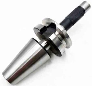
CNC 가공을 위한 공구 교정 방법
공구 교정은 CNC 공작기계의 기계 좌표계에서 공작물 좌표계를 설정하는 과정입니다., 공작물 좌표계의 원점을 프로그래밍 원점과 일치시키는 것. 시험절삭 또는 비접촉 방식으로 공작기계 좌표계의 공구 끝 프로그래밍 지점과 X 및 Z 방향의 가공 원점 사이의 거리를 측정합니다., 값을 기계 매개변수로 설정합니다.. 프로그램 호출을 통해, 공작물의 좌표계가 설정되었습니다.. 프로그램 내 기준점의 절대 좌표값은 설정된 공작물 좌표계의 원점을 기준으로 합니다., 부품의 윤곽이 처리됩니다..
CNC 선반에서 칼을 교정하는 방법에는 여러 가지가 있습니다., 시험 절단 방법은 작업에 일반적으로 사용됩니다.. FANUC을 소개합니다.-0I CNC 선반 일반적으로 사용되는 교정 도구 방법.
1. 측정 및 입력 도구 오프셋 방법
1) 선택한 도구를 사용하여 공작물의 외부 원을 시험 절단합니다., 도구를 X 방향으로 정렬합니다.. 수동 운전 모드에서, 바깥쪽 원을 잘라보세요, X 방향을 변경하지 않고 유지, 도구는 Z축을 따라 종료됩니다.. 버니어 캘리퍼스를 사용하여 절단된 외부 원의 직경 값 α를 측정합니다., 그리고 “오프셋” 형상 보정 매개변수 설정 인터페이스로 들어가는 버튼. 공구보정 X 위치로 커서 이동, Xα를 입력하세요, 그리고 소프트 키를 클릭하세요 [측정하다]. 수치 제어 시스템은 공작 기계 좌표계에서 X 방향의 현재 공구 끝 좌표를 자동으로 계산합니다., X 방향으로 공구 교정이 완료됩니다..
공작기계 교정
2) 선택한 도구를 사용하여 끝면을 자르고 Z 방향으로 도구를 보정합니다.. 수동 운전 모드에서, 공구는 공작물의 끝면을 중심으로 절단합니다.. 그런 다음 Z 방향은 움직이지 않습니다., 도구는 X 방향으로 종료됩니다.. 형상 보정 매개변수 설정 인터페이스로 들어갑니다., 공구 보정 Z 좌표의 해당 위치로 커서를 이동합니다., Z0을 입력, 누르다 [측정하다] 소프트 키, 해당 공구 오프셋이 자동으로 입력됩니다., 그리고 도구 세팅이 완료되었습니다. 가공원점을 공작물의 오른쪽 끝단 중앙에 설정하는 방법입니다., 일반적인 샤프트 부품에 흔히 사용되는 방식입니다.. 좌우대칭 부분인 경우, 가공 원점은 공작물의 대칭 중심에 설정되어야 합니다., 그런 다음 Zβ를 입력하십시오., β는 부품 축 길이의 절반입니다..
그런 다음 공구의 기하학적 크기와 설치 위치에 따라 공구 노즈 아크 반경 R과 공구 위치 번호 T의 값을 입력합니다., 예를 들어:
아니오를 위해. 1 도구, 공구 끝 호의 반경은 R=0.8mm입니다., No에 해당하는 위치로 커서를 이동합니다.. 1 R 아래의 도구, 키 입력 0.8, T의 해당 위치에 공구 위치 번호를 입력하세요., 그리고 누르세요 “입력” 입력하다, 그런 다음 처리에 사용할 수 있습니다..
2. 공작물 회전 후 Z 방향 교정 칼
공작물을 회전시킨 후, 가공은 가공 후 부품의 전체 길이를 보장해야 합니다.. 그러므로, 칼은 두 번 보정해야 합니다. X 방향은 이전 공구 세팅 방법과 동일합니다.. Z 방향 공구 설정 단계는 다음과 같습니다.:
공작물의 끝면을 중앙으로 자릅니다., Z 방향을 그대로 유지, X 앞으로 버튼을 누르세요, 도구가 종료됩니다.. Z 방향의 공작물 영역 전체 길이를 Z1로 측정합니다., 필요한 공작물의 총 길이는 Z입니다., 길이 차이는 Δ=Z1-Z입니다.. 프로그램을 실행하기 전에, 먼저 O점을 가공 원점으로 설정해야 합니다. (그림 참조 1), 형상 보정 매개변수 설정 인터페이스로 들어갑니다.. 커서를 Z좌표 위치로 이동, ZΔ를 입력하세요, (Δ는 새로 생성된 공작물 좌표에서 공구 끝의 현재 위치의 Z 좌표 값입니다.), 누르다 [측정하다] 소프트 키, 해당 공구 오프셋이 자동으로 입력됩니다..
3. G92는 공작물 좌표계를 설정합니다.
1) 외부 선삭 도구를 사용하여 먼저 외부 원을 선회해 보세요.. 바깥쪽 원의 직경을 측정한 후, 공구는 Z축의 양의 방향으로 후퇴됩니다., 그리고 스핀들이 멈춥니다.. 이때 공작기계 좌표계에서 공구의 절대좌표값 X1을 기록해 둡니다., 동시에 외부 원 직경 D를 측정합니다..
2) 끝면을 중앙으로 자릅니다., X는 움직이지 않는다, Z 방향으로 나가세요.. 이때 공작기계 좌표계에 공구의 절대좌표값 Z1을 적어주세요;
3) 출발점을 선택하세요. 시작점은 공작물 외부에서 선택해야 합니다.. 시작점을 오른쪽 끝면 중심에서 X방향으로 50mm, Z방향으로 50mm로 설정한 경우. 그러면 기계 좌표계의 시작점 위치 X = X1-D+100.0 (직경 프로그래밍), Z=Z1+50.0;
4) 도구를 조정하여 지점에 도달하세요.. G92에서 설정한 공작물 좌표계로 프로그램을 실행하기 전, 공구를 위쪽 위치로 조정해야 합니다.. 아래와 같은 방법:
먼저 수동 상태에서 시작점에 가까운 위치로 도구를 이동합니다., 그런 다음 핸드휠로 배율을 조정하여 정확한 위치에 도달합니다.;
5) 이때, 프로그램의 시작점은 다음과 같아야합니다.: G92 X100.0 Z50.0
설명:
(1) 이 지침을 실행하기 전에 도구를 보정해야 합니다., 공구 팁은 공작 기계를 조정하여 프로그램에서 요구하는 시작점 위치에 배치되어야 합니다.;
(2) G92 명령을 실행하면 공작 기계가 움직이지 않습니다.. 시스템이 기존 좌표 값을 새 좌표 값으로 바꾸도록 하세요., 이를 통해 새로운 좌표계를 구축.
공구를 확인하기 위해 시험 절단 방법을 사용할 때, 검증 도구의 오류는 주로 공작물의 시험 절단 후 측정 오류와 작업 중 육안 검사로 인한 오류에서 발생합니다.. 공구 설정 오류를 줄이기 위한 주요 조치는 다음과 같습니다.: 태도가 엄격해야 한다, 수술은 조심해야 해, 판독값이 정확해야 합니다.; 처리할 때, 공작 기계의 반복 위치 정확도가 공구 설정 정확도에 미치는 영향과 공구 위치 지점의 설치 높이가 공구 설정 정확도에 미치는 영향을 고려하십시오.; 도구 세팅 후, 공구 보정 값은 공구로 가공된 부품의 실제 크기와 프로그래밍된 크기 사이의 오류에 따라 수정되어야 합니다..
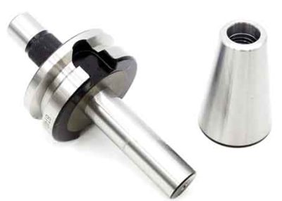
수치 제어 선반에는 다양한 제어 시스템이 있습니다.. 도구 교정 방법에는 수동 교정이 포함됩니다., 공작 기계의 외부 교정기 교정, 및 자동 교정. 수동 도구 설정은 다음 모드를 채택합니다. “시험 절단 측정 조정”, 그것은 간단하고 경제적이다, 공작 기계에서 오랜 시간이 걸립니다, 그리고 큰 오류가 있습니다. 공구 세팅용 캘리브레이터를 사용하면 각 칼날의 길이와 표준 칼날의 길이 차이를 자동으로 계산할 수 있습니다., 시스템에 저장하고. 다른 부분을 가공할 때, 표준 칼만 필요합니다., 작업 지원 시간을 크게 절약해줍니다.. 게다가, 공구 세팅을 위해 공구 세팅 장비를 사용하면 측정 중 오류를 제거하고 공구 세팅의 정확성을 크게 향상시킬 수 있습니다.. 공구 끝 감지 시스템으로 자동 공구 설정이 실현됩니다.. 툴팁이 설정된 속도로 터치 센서에 접근합니다.. 공구 끝부분이 센서에 닿아 신호를 보내면, CNC 시스템은 그 순간의 좌표 값을 즉시 기록하고 자동으로 공구 보정 값을 수정합니다.. 외부 공구 세팅기의 매개변수 입력 원리와 자동 공구 세팅은 수동 공구 세팅과 유사하지만, 측정 원리와 방법이 다릅니다, 자동화 정도가 높다, 그리고 업무 효율성이 향상됩니다.
각 도구 교정 방법에는 고유한 장점과 단점이 있습니다., 운영자는 실제 필요에 따라 유연하게 사용할 수 있습니다.. 이런 식으로, 전체 공구 세팅 작업이 간단합니다, 가공 품질을 보장할 수 있습니다., 보조 시간을 크게 절약할 수 있습니다., 생산 효율성을 효과적으로 향상시킬 수 있습니다..