 English
 العربية
 中文(漢字)
 Čeština
 Dansk
Dansk Nederlands
 Suomi
Suomi Français
 Deutsch
 Italiano
 日本語
日本語 ಕನ್ನಡ
ಕನ್ನಡ 한국어
한국어 Português
 Русский
 Slovenčina
 Español
 Svenska
 Türkçe
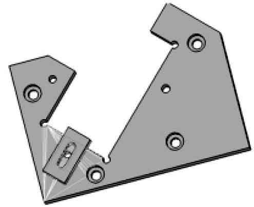
3차원 디자인 소프트웨어의 개발로 저비용의 여건 제공, 짧은 기간, 위치 결정 장치의 설계 및 설계. 그리고 검증을 위해 CNC 가공 부품을 시뮬레이션할 수 있습니다.. 수치 1 YZ 및 ZX 평면에 대해 45° 각도의 일반적인 금속 부품을 보여줍니다.:
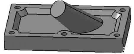
특수 구조의 CNC 가공 부품
수치 1 부품 CNC 가공 계획 선택
특별한 공간 구조를 가진 이런 종류의 부품은 일반적으로 2 CNC 가공 방법의 종류:
① 공작기계의 성능을 향상시킨다, 그건, 기존 2.5축 또는 3축 CNC 공작 기계를 2.5축 또는 3축 CNC 공작 기계보다 더 많이 사용 5 축;
② 적합한 위치 결정 장치를 설계하고 기존 장비를 사용하여 가공합니다..
처리 비용을 고려하면, 두 번째 옵션은 분명히 더 이상적인 선택입니다. 다음은 이 부품의 위치 고정 장치를 설계하는 것입니다., CATIA 소프트웨어를 사용하여 솔리드 모델링을 수행합니다., 집회, 간섭 감지, Fixture의 각 구성 요소에 대한 정확도 분석 및 정확도 분석. 가상 가공을 위해 설계된 고정 장치를 CNC 가공 모듈로 가져와 설계의 타당성과 정확성을 확인합니다..
포지셔닝 픽스처의 설계 및 3D 모델링
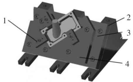
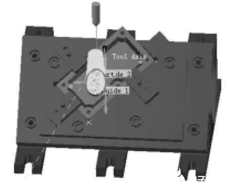
가공된 부품의 특성을 고려한, 처리의 정확성 보장, 그리고 Fixture의 적용 범위를 향상시키기 위해, 포지셔닝 고정 장치는 모듈식 결합 고정 장치로 설계되었습니다., 그림과 같이 2. 정착물은 주로로 구성됩니다 4 부속: 포지셔닝 브래킷, 포지셔닝 플레이트, 가이드 모듈 및 포지셔닝 클램프. 포지셔닝 브래킷은 전체 고정 장치의 초석입니다., 포지셔닝의 성향을 직접적으로 결정하는 것, 그리고 다른 부품들도 그 위에 설치되어 있습니다.
3위치 결정 장치의 D 솔리드 모델
수치 2 포지셔닝 픽스처의 3차원 입체 모델
1. 포지셔닝 클립
2. 포지셔닝 브래킷
3. 포지셔닝 플레이트
4. 지도 모듈
포지셔닝 플레이트는 가이드 모듈을 포지셔닝 브래킷에 설치하는 데 사용됩니다., 45°의 경사로 가공할 공작물의 바탕면의 크기와 형상이 변경되는 경우, 가이드 모듈의 구조와 크기만 변경하면 됩니다.. 고정을 위해 포지셔닝 플레이트에서 적절한 위치를 선택하면 포지셔닝 클램프를 더 넓은 범위에 적용할 수 있습니다.. 가이드 모듈과 포지셔닝 클램프의 설계는 가공되는 부품의 구조와 형태에 따라 이루어져야 합니다., 가공할 부품의 외부 표면과 일치하도록, 위치 지정 클램프를 쉽게 설치할 수 있도록 높이가 동일해야 합니다.. 포지셔닝 클램프는 일반적으로 3점 포지셔닝으로 설계 및 설치됩니다., 그리고 포지셔닝 플레이트와 협력하여 한계를 실현합니다. 6 가공할 부품의 자유도.
포지셔닝 픽스처의 정적 간섭 검사
설계된 치구의 구성요소가 가공되고 조립될 수 있는지 확인하기 위해, 그리고 그것의 포지셔닝 기능을 달성할 수 있습니다, 간섭 감지는 고정 장치에서 수행되어야 합니다..
정적 간섭 분석에는 고정 장치 사이의 간섭과 고정 장치와 공작물 사이의 간섭이 포함됩니다.. 각 고정 장치는 여러 장치로 구성됩니다., 완성에는 포지셔닝과 클램핑이 포함됩니다.. 제한된 공간과 각 유닛의 복잡한 구조로 인해, 고정 장치의 디자인은 일반적으로 레이어별로 디자인됩니다., 공간의 여백 조절이 어렵고 간섭이 쉽다.. 게다가, 공작물의 모양이 복잡하다, Fixture Unit의 위치나 구조에 따라 공작물이 올바르게 설치되지 않을 수 있습니다..
고정 장치의 동적 충돌 감지
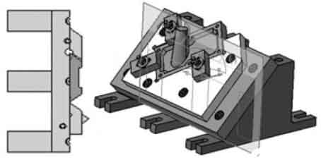
수치 3 정적 간섭 감지의 개략도
아래 “DMU공간분석” CATIA의 모듈, 설비에 대한 정적 간섭 분석 수행, 충돌 감지를 사용하십시오 “CheckClash” 그리고 섹션 도구 “단면 정의” 고정물을 감지하기 위해.
동적 간섭 분석
사용 “DUMFitting” 조립된 제품을 검사하기 위해 CATIA에서 제공하는 모듈. 조립 중 부품의 이송 경로를 기록할 수 있습니다., 부품 조립 시 움직이는 부품에 필요한 동적 공간 분석, 부품 간의 간섭을 감지합니다.. 먼저 스위치를 “조립 설계” 에 “DUMFitting” 기준 치수, Fixture Assembly에 따라 각 조립 경로를 제공합니다., which includes the transfer distance information of each component. The purpose is to be able to obtain the specific interference position and depth when the interference occurs, then establish the assembly simulation in order, and finally open the “collision” analysis. The analysis result is shown in Figure 4.
Schematic diagram of static interference detection of fixture
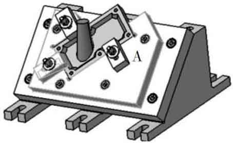
수치 4 Dynamic collision detection
Area A shown in Figure 4 is the location where interference occurs, and its specific display is shown in Figure 5. Interference occurs between the positioning clamp and the guide module. Through the analysis of the interference information, it is concluded that the positioning clip collides with the assembly path of the guide module during the assembly process. For interference appears, make the following changes to fixture: 포지셔닝 포인트와 클램핑 포인트를 변경하지 않고 유지한다는 전제하에, 장치의 다른 부분의 공간 위치 또는 일부 크기 매개변수를 변경합니다..
고정물의 검출 간섭 영역
수치 5, 간섭이 발생하는 영역
CNC 시뮬레이션 처리
사용 “처리” 공작물 가공 시 공구가 치구와 충돌하는지 확인하기 위해 공작물에 CNC 가공을 수행하는 CATIA에서 제공하는 모듈, CNC 가공의 타당성을 검증하기 위해. 충돌이 발생하는지 직관적으로 관찰할 수 있도록, 이 기사에서는 공작물의 공간적 경사를 사용하여 드래프트 실린더의 외부 윤곽을 처리하도록 선택합니다.. 첫 번째, 조립된 고정 장치를 다음으로 전환합니다. “표면 가공” 아래에 “가공” 수행할 모듈 “윤곽 중심” (윤곽 중심 마무리) 가공된 부품의 외부 표면에;
그런 다음 팝업 대화 상자에서 가공할 부품으로 가공 영역을 선택합니다., 적절한 도구 경로 매개변수를 선택합니다., 주행 가이드 라인 선택을 포함하여, 적절한 도구 매개변수 및 도구 종료 경로;
마지막으로, 공구 경로 라인을 생성하기 위해 CNC 시뮬레이션 처리가 수행됩니다., 그림과 같이 6.
CNC 가공 부품으로 생성된 공구 경로 선
수치 6, 생성된 공구 경로 선
고정 장치의 총 위치 오류:
(여기서 δK= 공작물의 프로세스 크기 공차)
위 사례는 CATIA의 3차원 가상 설계 능력을 활용하여 효과적으로 비용을 절감하고 설계 및 생산 주기를 단축할 수 있습니다., 포지셔닝 설비의 설계 및 기능 테스트; 전체적인 디자인 구성에서는, the computer completes the process from design to assembly to simulation processing on CNC machine tools, including static and dynamic interference analysis. This is unmatched by traditional design methods, and it is also an inevitable trend in the development of modern fixture industry.