 English
 العربية
 中文(漢字)
 Čeština
 Dansk
Dansk Nederlands
 Suomi
Suomi Français
 Deutsch
 Italiano
 日本語
日本語 ಕನ್ನಡ
ಕನ್ನಡ 한국어
한국어 Português
 Русский
 Slovenčina
 Español
 Svenska
 Türkçe
도구 및 금형 제조 시 복잡한 윤곽이 나타납니다., 대량생산되는 제품이고. CNC 공작기계가 등장하기 전, 자동차산업에서 사용되는 단조금형과 금형은 주로 수작업으로 제작되었습니다.. 1970년대 이후, CNC 공작 기계는 공구 및 금형 제조에 널리 사용되었습니다.. 복잡한 프로파일의 기본 윤곽은 일반적으로 밀링으로 처리됩니다., 주변 CNC 공작기계는 초기에 3축 연동으로 설정되어 있습니다..
After entering the 1980s, five-axis milling machines have been widely used in complex surface processing. The contour of the workpiece after milling is very close to the final shape of the workpiece, but the last finishing process is still manual. In the late 1980s, high-speed cutting technology gradually developed and matured, and its application in industrial production has been continuously improved in terms of machine tools, cutting tools and other related technologies. Since high-speed cutting can double the feed speed, the feed pitch can be reduced without reducing production efficiency. This provides a prerequisite for improving the shape accuracy of the workpiece and reducing the surface roughness. 현재, most of the workpieces processed by high-speed milling no longer need the last manual processing procedure, but can be directly put into use.
5-복잡한 프로파일의 축 가공
New tool materials: such as alumina-based ceramics, silicon nitride-based ceramics, cermets, 초경합금, especially the continuous development of superhard coatings, making hard face milling possible. The mold surface can be milled to shape after quenching, thereby avoiding deformation caused by quenching after milling. This not only simplifies the machining process, but also improves the accuracy of the workpiece.
게다가, with the application of precision forging in die manufacturing, the die blank after forging already has its designed basic shape, 나머지 가공 여유는 전체 블랭크의 밀링에 비해 미미합니다.. 이 경우, 밀링 외에도, 고효율 분쇄로 가공할 수도 있습니다.. 하드 페이스 밀링과 비교, 고효율 연삭은 공작물의 형상 정밀도를 향상시킬 수 있을 뿐만 아니라, 또한 공작물의 표면 거칠기를 향상시킵니다.. 고효율 분쇄 방법이 많이 있습니다, 일반적으로 구형 연삭 휠을 사용한 고속 연삭 및 작은 직경의 벨트 휠을 사용한 벨트 연삭.
밀링 커터의 종류
공구 및 금형의 3차원 자유 형태 표면은 일반적으로 5축 머시닝 센터에서 처리됩니다.. 공작물의 재질은 대부분 합금강 또는 공구강이므로, the structure of the machine tool and the numerical control system must consider the requirements of productivity and workpiece accuracy in the processing process, and make appropriate layout and optimization based on this. In order to ensure that the machine tool does not undergo too much deformation when cutting various mold materials, the machine tool stiffness should be the first priority when determining the machine layout. Larger axis machining center, most of a gantry structure, some small-sized five-axis machining center is also sometimes used high column structure.
Since the beginning of the 1990s, almost all complex shapes have been processed by high-speed cutting in production. The purpose is to improve production efficiency, reduce product cost, 동시에 공작물의 형상 정확도를 향상시키고 표면 거칠기를 줄입니다.. 고속 절단 요구를 충족시키기 위해, 공작기계의 스핀들은 거의 예외 없이 전동 스핀들을 사용한다.. 스핀들 속도는 사용되는 공구의 직경에 따라 지속적으로 변합니다., 속도는 분당 수천 회전에서 분당 수만 회전까지 다양합니다.. 슬라이딩 테이블의 구동방식도 기존 머시닝센터와는 달리 고속절삭이 가능하다. 고속 드라이브 너트 나사 조립 및 리니어 모터 드라이브를 갖춘 일반적으로 사용되는 시스템, 최대 공급 속도는 100m에 도달할 수 있습니다. / 분 이상.
CNC 가공 복합 캐비티 표면의 외관도
복잡한 표면을 처리할 때, the CNC system of the machine tool must also meet some special requirements. 예를 들어, CNC machining programs for complex surfaces are generally generated on CAD/CAM software. A profiled program often requires several megabytes (Byte) of storage space, and it is no longer possible to transfer NC programs with a floppy disk. 그러므로, the CNC system must have the function of networking with other computer systems in order to receive the CNC program directly from the CAD/CAM. 게다가, the numerical control system must also adopt advanced control technology, first of all, it requires the function of LookAhead. 다시 말해서, before the machine tool processes a certain track, the data system analyzes the surface to be processed in advance. 곡면의 각 점의 곡률과 인접한 각 점의 연결 관계에 따라, 공작물의 정확성 보장을 전제로 공작 기계의 이송 속도를 적절하게 조정하여 최고의 생산성을 달성합니다.. 처리 중 동적 오류를 줄이기 위해, 기존 탠덤 시스템을 사용하는 새로운 서보 오류 수정 데이터는 더 이상 비례 적분 미분이 아닙니다. (PID) 제어 장치, 위치 및 속도 상태 매개변수를 보상하여 상태 조절기를 사용하는 대신. 이러한 종류의 조정기를 사용하면 드라이브 히스테리시스 오류를 완전히 제거할 수 있습니다., 간격이나 마찰로 인한 비선형 오류를 보상합니다., 공작 기계의 특정 진동을 상쇄할 수도 있습니다.. So as to meet the requirements of improving the shape accuracy of the workpiece and reducing the surface roughness.
Setting of the cutting path of the cavity surface
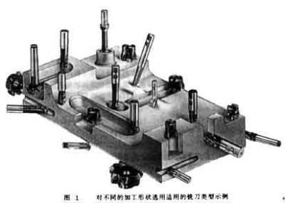
The tool system plays a decisive role in the production efficiency and processing quality when processing complex profiles. When selecting a cutting tool system, we must first start from the geometry of the parts to be processed, and reasonably use the types of cutting tools. 그림과 같이 1, the geometry of each part is very different. If only a ball-end milling cutter is used for processing, a ball-end milling cutter with a small diameter must be selected, which makes it difficult to improve processing efficiency. 게다가, the arc radius of some parts is so small that it cannot be processed even with a small ball end mill. 그러므로, taking into account the requirements of both production efficiency and workpiece shape, other types of milling cutters must be equipped on the five-axis machining center for processing complex profiles, such as end mills and three-face milling cutters.
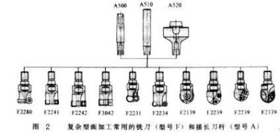
수치 2 shows some types of milling cutters. As long as the size permits, regardless of the shape of the tool, the cutting edge should be a milling insert with a convertible clamp. Such knives can be combined in a variety of ways because of the blade and the body, and the blade and the body can be produced by different companies. 그러므로, large-scale specialized production can be formed, which not only helps to improve the quality of the tool, but also helps to reduce the production cost of the tool.
현재, 시중의 대부분의 인덱서블 블레이드는 CVD 코팅 카바이드 블레이드를 사용합니다.. 더 높은 유사 내마모성을 달성하기 위해, 인덱서블 인서트는 모두 다층 코팅입니다.. Bizhi Al2O3는 블레이드의 화학적 안정성을 향상시킬 수 있습니다.. TiN 및 TiCN은 블레이드의 내마모성을 향상시킬 수 있습니다.. 칼날의 예리함을 높이기 위해, 저온 CVD 방식 외에, 코팅은 PVD 방법으로도 생산할 수 있습니다.. 일부 처리에는 블레이드에 대한 매우 엄격한 요구 사항이 있습니다.. 칼날은 마감면의 거칠기를 줄이기 위해 날카로운 절단면을 가져야 합니다., 또한 공작물의 형상 정확성을 보장하기 위해 높은 내마모성을 가지고 있습니다.. 이 경우, 여러 코팅을 조합하여 사용해야 합니다.. 일부 블레이드의 사용이 완벽하다는 것을 확인하기 위해, the number of coating layers can be as high as 100.
The life of the tool is closely related to the feed rate, cutting speed and depth of cut. The optimal cutting amount is often a small range, which should be determined according to the specific tool and workpiece material.
게다가, cutting strategies such as: The planning of the tool path, the normal vector of the tool axis surface (the normal direction of the surface at this point) or the different methods along the surface tangent vector (the tangent direction of the surface at this point), 등., are also a key factor for processing complex surfaces . It not only affects the surface roughness of the processed workpiece, but also affects the shape and dimensional accuracy of the workpiece. 수치 3 원통형 표면을 가공할 때 사용되는 다양한 절단 전략을 보여줍니다.. 원주 방향 절단용, 공구 경로는 2축 연결로 보간되어야 합니다.. 모선 방향을 따라 절단할 때, 도구는 단일 축 보간만 수행하면 됩니다.. 게다가, 절삭 방법에 따라 공구 마모에 큰 차이가 있습니다.. 하향 밀링 중 공구 마모는 상향 밀링보다 현저히 낮습니다., 왕복 밀링 중 마모는 단방향 밀링보다 훨씬 큽니다..
가공 공정의 안정성을 향상시키기 위해, 절단 전략을 최적화할 때, 절단의 연속성이 보장되어야 합니다., 그리고 절삭 시간을 단축하기 위해서는 절삭 동작과 아이들 스트로크를 최대한 줄여야 합니다.. When the rough milling of steel, must ensure continuous climb milling, to minimize the peak of the cutting blade during cutting of the amount of fluctuation.
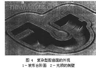
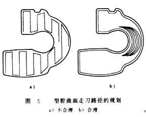
When processing the workpiece shown in Figure 4, if the row cut trajectory section processing shown in Figure 5a is used; The movement of the tool is very unreasonable, the cutting conditions are very unsatisfactory, the processing time is 33min, and the surface roughness of the workpiece is 6-9μm. If you switch to the circle-cutting path shown in Figure 5b for processing, the processing time is about 27 분. 동시에, the roughness of the workpiece can also be reduced to 2 ~ 4μm.