 English
 العربية
 中文(漢字)
 Čeština
 Dansk
Dansk Nederlands
 Suomi
Suomi Français
 Deutsch
 Italiano
 日本語
日本語 ಕನ್ನಡ
ಕನ್ನಡ 한국어
한국어 Português
 Русский
 Slovenčina
 Español
 Svenska
 Türkçe
“3축의 차이점은 무엇인가요?, 3+2 중심선, 4-중심선, 우리가 흔히 언급하는 5축 CNC 가공 방식과?”
3-axis CNC machining method
3-axis CNC machining method
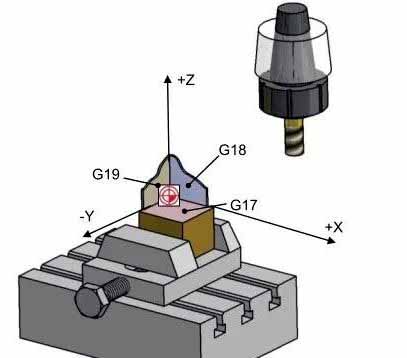
The 3-axis CNC machining is processed by linear feed axes X, 와이, 그리고 Z. Processing characteristics: The direction of the cutting tool remains unchanged during the movement along the entire cutting path. The cutting state of the tool tip cannot be perfect in real time.
3+2 축 가공 방법
3+2 축 가공 방법
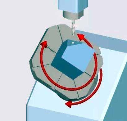
The two rotating axes fix the cutting tool in an inclined position first, and then perform processing by the feed axes X, 와이, 그리고 Z. This kind of machine tool is also called positioning 5-axis machine tool. The CYCLE800 function of Siemens can be used for programming processing. CYCLE800 is a static plane transformation, which can define the rotating work plane in space by 3+2 축 가공 (such as rotary head or rotary table). In this work plane, 2D or 3D CNC machining operations can be programmed.
Processing features of 3+2 중심선: The rotary axis always rotates to the position where the machining plane is perpendicular to the tool axis for machining, and the machining plane remains fixed during machining.
4-축 가공: 일반적으로, when the workpiece is not positioned in space, there are six degrees of freedom processing range, three linear displacement degrees of freedom of X, 와이, Z and three degrees of freedom of rotation displacement corresponding to the machined parts A, 비, 씨 .
The characteristics of 4-axis machining: 일반적으로, the parts machining center corresponding to the 4th axis pair is used in the index-controlled machine tool. And add a rotation axis to the general machining center.
5-축 가공 방법
5-축 가공 방법
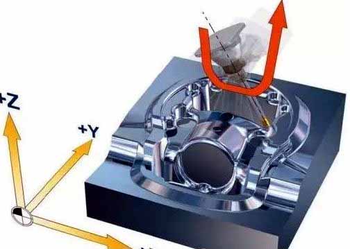
5-axis machining consists of linear interpolation movement of feed axes X, 와이, Z and any 5 axes of X, 와이, Z rotation axes A, 비, and C. 지멘스’ motion conversion instruction TRAORI can well support 5-axis conversion.
Features of 5-axis machining: The tool direction can be optimized during the movement along the entire stroke, and the tool can be moved linearly at the same time. 이런 식으로, the optimal milling state can be maintained on the entire path.