製品カテゴリ
- CNCフライス加工サービス 31
- CNCスタンピングサービス 0
- CNC板金 0
- ラピッドプロトタイピング 12
- スタンピングダイ 0
- チタン合金部品 4
- ステンレス鋼部品 5
- アルミフライス部品 14
- CNC旋削サービス 16
カスタマイズされた大型CNC機械加工部品
加工部品のCNC加工の技術的課題は多岐にわたります。. 以下は、分析とレビューが必要な主要なコンテンツを提案するためのプログラミングの可能性と利便性を組み合わせたものです。.
Process analysis of CNC machining parts
加工部品のCNC加工の技術的課題は多岐にわたります。. 以下は、分析とレビューが必要な主要なコンテンツを提案するためのプログラミングの可能性と利便性を組み合わせたものです。.
1. The dimensioning should conform to the characteristics of CNC machining
In CNC programming, the size and position of all points, lines, and surfaces are based on the programming origin. したがって, it is best to give the coordinate size directly on the part drawing, or try to quote the size with the same datum.
2. The conditions of geometric elements should be complete and accurate
In programming, programmers must fully grasp the geometric element parameters constituting the contour of the part and the relationship between the geometric elements. Because all geometric elements of the contour of the part must be defined during automatic programming. When manually programming, the coordinates of each node must be calculated. No matter which point is unclear or uncertain, programming cannot be performed.
しかし, due to inadequate consideration or neglect by part designers in the design process, there are often incomplete or unclear parameters, のような: arc and straight line, arc and arc are tangent or intersected or separated.
したがって, when reviewing and analyzing the drawings, you must be careful and contact the designer in time if you find any problems.
3. Reliable positioning reference
CNC加工では, the machining processes are often concentrated, and it is very important to locate on the same reference. したがって, it is often necessary to set some auxiliary datums or add some process bosses on the blank.
4. Unified geometry type or size
It is best to adopt a uniform geometric type or size for the shape and cavity of the parts. This can reduce the number of tool changes, and it is also possible to use control programs or special programs to shorten the program length. The shape of the parts is as symmetrical as possible, which is convenient for programming using the mirror machining function of the CNC machine tool to save programming time.
Clamping of machined parts
- Basic principles of positioning and installation
When machining parts on a CNC machine tool, the basic principle of positioning and installation is to select a reasonable positioning datum and clamping plan. Pay attention to the following points when choosing:
1. Strive to unify the design, process and programming calculation benchmarks.
2. Minimize the number of clamping times, and process all the surfaces to be processed after positioning and clamping once.
3. Avoid the use of machine-occupied manual-adjustable processing schemes to give full play to the effectiveness of CNC machine tools.II. Basic principles for selecting fixtures
The characteristics of CNC machining put forward two basic requirements for the fixture:
One is to ensure that the coordinate direction of the fixture is relatively fixed with the coordinate direction of the machine tool;
The second is to coordinate the size relationship between the parts and the machine coordinate system. 加えて, the following points should be considered:
1. When the batch of parts is not large, modular fixtures, adjustable fixtures and other general fixtures should be used as much as possible to shorten production preparation time and save production costs.
2. Only consider the use of special fixtures during mass production, and strive for a simple structure.
3. The loading and unloading of parts should be fast, convenient and reliable to shorten the machine stop time.
4. The parts on the fixture should not hinder the machining of the surfaces of the parts by the machine tool, あれは, the fixture should be open. Its positioning and clamping mechanism components cannot affect the tool in the machining process (such as collisions, 等).
Program structure
A program segment is a continuous group of words that can be processed as a unit, and it is actually a section of a program in a CNC machining program. The main body of the part processing program is composed of several program segments. Most program segments are used to instruct the machine tool to complete or execute a certain action.
The block is composed of size characters, non-size characters and block end instructions. When writing and printing, each block generally occupies one line, and the same is true when the program is displayed on the screen.Program format
The conventional processing program is composed of start character (single row), program name (single row), program body and program end instruction (generally single row). There is a program end character at the end of the program.
The program start character and the program end character are the same character:
It is% in ISO code and ER in EIA code. The program end instruction can be M02 (program end) or M30 (paper tape end).
CNC machine tools generally use stored programs to run. 現時点では, the common points of M02 and M30 are:
After completing all other commands in the current block, it is used to stop the spindle, coolant and feed, and reset the control system.
M02 and M30 are completely equivalent when used on some machine tools (systems), while the following differences are used on other machine tools (systems): When the program is ended with M02, the cursor will stop at the end of the program after the automatic operation ends; When the program is terminated by M3O, the cursor and screen display can automatically return to the beginning of the program after the automatic operation is over, and the program can be run again by pressing the start button. Although M02 and M30 are allowed to share a block with other program words, it is better to list them in a single block or share a block with the sequence number only.The program name is located before the main body of the program and after the start of the program, and it usually occupies a line on its own. The program name has two forms:
One is composed of prescribed English characters (usually O), followed by several digits. The maximum allowable number of digits is stipulated by the manual, and the two common ones are two digits and four digits. This form of program name can also be called a program number. Another form is that the program name is composed of English characters, numbers or a mixture of English and numbers, and a “-” sign can be added in the middle. This form makes the user naming procedure more flexible. 例えば, the program for the third process of machining the flange with the part drawing number 215 on the LC30 CNC lathe can be named LC30-FIANGE-215-3. This brings great convenience to use, storage and retrieval. The format of the program name is determined by the CNC system.
%
O1001
N0 G92 X0 Y0 Z0
N5 G91 G00 X50 Y35 S500 MO3
N10 G43 Z-25 T01.01
N15 G01 G007 Z-12
N20 G00 Z12
N25 X40
N30 G01 Z-17
N35 G00 G44 Z42 M05
N40 G90 X0 Y0
N45 M30
%Programming section format
The rules for the arrangement of words, characters and data in a program segment are called block format. The fixed sequence format and separator (HT or TAB) block format have been used in CNC history. When these two program segment formats have passed, the word address variable program segment format is widely used at home and abroad, also known as the word address format.
In this format, the program word length is not fixed, and the number of program words is also variable. Most CNC systems allow the sequence of program words to be arranged arbitrarily, so they belong to the variable block format. しかし, ほとんどの場合, for the convenience of writing, inputting, checking and proofreading, program words are arranged in a certain order in the program segment.
The programming instructions of CNC machine tools use detailed formats to classify and specify the details of programming: The characters used in programming, the sequence and word length of the program words in the program segment, 等. 例えば:/ NO3 G02 X+053 Y+053 I0 J+053 F031 S04 T04 M03 LF
The detailed format classification description of the above example is as follows: N03 is the sequence number of the program segment; G02 means that the processing track is a clockwise arc; X+053, Y+053 indicate the coordinates of the end point of the arc to be processed; I0, J+053 represent the center coordinates of the arc to be processed; F031 is the processing feed rate; S04 is the spindle speed; T04 is the tool number of the tool used; M03 is an auxiliary function command; LF block end instruction; /Select instructions for skipping. The function of skip selection instruction is: On the premise that the program remains unchanged, the operator can choose whether to execute or not to execute the blocks in the program with skip selection instructions. The method of selection is usually by turning the step selection switch on the operation panel to ON or OFF to realize that the program segment with “/” is not executed or executed.
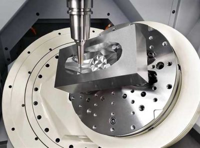
milwaukee wisconsin machining services
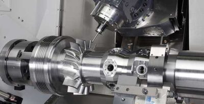
精密組立 機械加工部品のクランプ
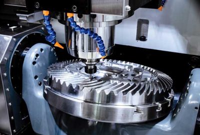
Programming of CNC machining steel parts
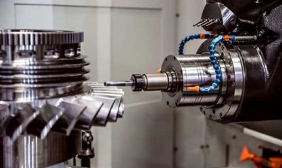
CNC machining parts different program structure
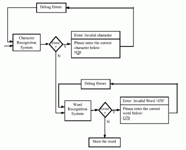
CNC machining components Program execution process
Execution of the program
This is sometimes encountered in the preparation of processing programs: A group of blocks appears multiple times in a program, or it is used in several programs. We can extract this group of program segments, name them and store them separately. This group of program segments is a subroutine. A subroutine is a section of processing program that can be called by appropriate machine control instructions, and it generally has an independent meaning in processing. The processing program where the instruction to call the subroutine of the first level is located is called the main program. The instruction of the subroutine is also a program segment, which is generally composed of the subroutine call instruction, the subroutine name, and the number of calls. The specific rules and formats vary from system to system. 例えば, it is also "call subroutine No. 55 once", FANUC system uses "M98 P55.", and American A-B company system uses "P55x".
Subroutines can be nested, あれは, layer by layer. The relationship between the upper level and the next level is the same as the relationship between the main program and the first level subroutine. The maximum number of layers that can be set depends on the specific CNC system. The form and composition of the subroutine are roughly the same as the main program: The first line is the subroutine number (name), the last line is the "subroutine end" instruction, and the main body of the subroutine is between them. しかし, the function of the main program end instruction is to end the main program and reset the CNC system. The instructions have been standardized, and each system uses M02 or M30; The function of the subroutine end instruction is to end the subroutine, return to the main program or the upper level subroutine. The commands are not unified in various systems, such as M99 for FANUC system, M17 for Siemens system, and M02 for system of American A-B company.
User macros (programs) can be used in CNC machining programs. The so-called macro program is a subroutine containing variables. The instruction that calls the macro program in the program is called the user macro instruction, and the function that the system can use the user macro program is called the user macro function. When executing, you only need to write the user macro command to execute its user macro function.
The biggest features of user macros are:
● Variables can be used in user macros;
●Can use calculation formulas, turning statements and various functions
●User macro commands can be used to assign values to variables.
CNC machine tools use group technology to process parts, which can expand batch size, reduce programming, and improve economic benefits. In the group processing, the parts are classified, and the processing program is compiled for this type of parts, instead of editing a program for each part. When processing the same type of parts with different sizes, the main convenience of using user macros is that variables can be used instead of specific values. When it comes to actual processing, it is only necessary to assign the actual size value of this part to a variable with a user macro command.
お問い合わせ
メールを待っています, 以内に返信させていただきます 12 必要な貴重な情報を何時間も入手できる.
 English
 العربية
 中文(漢字)
 Čeština
 Dansk
Dansk Nederlands
 Suomi
Suomi Français
 Deutsch
 Italiano
 日本語
日本語 ಕನ್ನಡ
ಕನ್ನಡ 한국어
한국어 Português
 Русский
 Slovenčina
 Español
 Svenska
 Türkçe


