What is milling? What is the process of milling? What parts can be machined by CNC milling? What precision can China mill parts achieve?
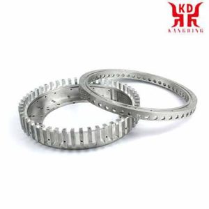
What is milling?
CNC milled parts
How are CNC milled parts manufactured?
CNC milled parts are machined on CNC milling machines with the help of rotating tools. CNC milling machines with different degrees of freedom of movement are used: 3-軸, 4-axis and 5-axis milling machines.
3-axis milling machines can only machine CNC milled parts from one accessibility direction. They are cheaper than the other types of milling machines. 4-axis milling machines have an additional axis of rotation for the milled part, for example for the production of spindles and other helical geometries. 5-axis milling machines can machine CNC milled parts from all sides, depending on the clamping, and also produce complex geometries.
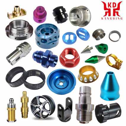
With our supplier network, we can manufacture a wide range of CNC milled parts for a wide variety of requirements.
We specialize in CNC machining, our automatic price calculation is constantly being expanded and currently covers components with the following properties.
Milling consists mainly of cutting the material that is machined with a rotary tool with several edges, called teeth, lips or carbide inserts, which executes programmed advance movements of the worktable in almost any direction of the three Possible axes on which the table where the part to be machined is fixed can be moved.
With the increasing use of numerical control milling machines, the milling operations that can be carried out with this type of machine are increasing, and thus milling has become a multipurpose machining method. The development of the tools has also contributed to create new possibilities of milling in addition to considerably increasing the productivity, quality and accuracy of the operations carried out.
| Our manufacturing options for CNC milled parts
Component dimensions from 2 mm x 2 mm x 2 んん |
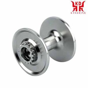
cnc milling parts
Milling tools
The milling tools are characterized by their outside diameter, the number of teeth, the pitch of the teeth (understood as the distance between two consecutive teeth) and the fastening system of the cutter on the machine.
Types of milling
In the universal milling machines using the appropriate accessories or in the numerical control milling machines the following Planning can be carried out.
The most frequent application of milling is face milling that aims to achieve flat surfaces. For the face milling milling cutters with interchangeable carbide inserts are generally used, there is a very varied range of diameters of these mills and the number of inserts that each milling cutter mounts. インサートメーカーは、最初のオプションとして丸型インサートの使用、または代わりに 45 度の角度を使用することを推奨しています。.
四角フライス加工. スクエアミリングは正面フライス加工の一種で、加工する部品に垂直な段差を残すことから成ります。. このために, 四角いインサートが使用され、適切な方法でツールホルダーに配置されます。.
キューブミリング. 立方体化操作は垂直または水平フライス盤で非常に一般的であり、金属ダボや大理石や花崗岩などのその他の材料を後続の操作に適した立方体寸法に準備することから構成されます。. このフライス加工は、交換式インサート正面フライスカッターでも行われます。.
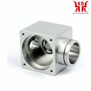
CNC フライス加工部品 フライス加工の種類
カットミーリング. One of the initial machining operations that must be carried out often consists of cutting the pieces to the determined length starting from commercial bars and profiles of a greater length. Band saws or milling machines equipped with cylindrical cutters are used interchangeably for industrial cutting of parts. What is significant about cutting burs is that they can be made of high-speed steel or hard metal. They are characterized by being very thin (on the order of 3 んん, although it may vary), having a large diameter and very fine teeth. An example of the characteristics of a cutter would be the following: diameter of 200 んん, thickness of 3 んん, diameter of the hole of 32 mm and 128 歯: Fine 128, Coarse 64.
Straight Grooving Milling. For milling straight grooves, cylindrical cutters with the width of the groove are generally used and often, 生産量を増やすために, カッターシャフトに複数のカッターが取り付けられており、加工の生産性が向上します。. 円柱状のイチゴが数個集まったものをイチゴ列または複合イチゴといいます。. 円筒バーは3つの切れ刃を持つのが特徴です。: 正面と両側. 超硬バーは非常に高価であり、したがって非常に大規模な生産でのみ使用されるため、高速度鋼バーがほとんどの用途で使用されます。.
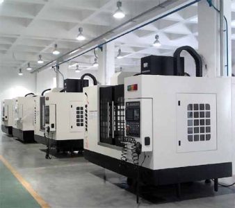
CNC フライス加工部品 フライス加工の種類
形状溝加工。. 溝に適した形状のバーを使用, T字型にすることができます, ダブテール, 等.
キー溝溝入れ. ハンドル付きの円筒形イチゴ, 俗語でバレリーナとして知られる, 軸に垂直な方向と平行な方向の両方に切断できるものを使用します。.
倣い加工におけるフライス加工. Round insert profile cutters are used for copy milling in order to be able to carry out machining operations in orographies and profiles of changing faces. There are two types of copy cutters: those with a half ball profile and those with a round or toric edge.
Cavity milling. In this type of operation, it is advisable to carry out a prior drilling and from there and with suitable milling cutters, approach the cavity machining, bearing in mind that the radii of the cavity must be at least 15% greater than the radius of the milling cutter.
Lathe-milling. This type of machining uses circular interpolation in numerical control milling machines and is used for both precision hole turning and external turning. The process combines the rotation of the workpiece and the milling tool, 円筒面の実現が可能. この表面は部品の回転中心線に対して同心であってもよい, または、フライス加工が上下に移動すると偏心する可能性があります. 軸方向の変位により、必要な長さを実現することが可能.
ねじ切り加工. ねじ切りフライス加工には、2 つの自由度で同時にヘリカル補間を実行できるフライス盤が必要です: ねじ山の螺旋の軸に対する部品の回転と、その軸の方向への部品の並進.
正面フライス加工. フライス加工を正面から攻撃する円筒状の螺旋バーを使用して実行されるフライス加工で構成されます。. 非常に高速での作業を可能にする数値制御フライス盤では、完全一体型超硬バーがますます使用されています。.
歯車フライス加工. 仕切り板を使用した万能フライス盤では歯車加工はほとんど行われなくなりました, ただし、歯車ホブ盤と呼ばれる特別な機械と、適切な歯モジュールの特別なフライスを使用して行われます。.
掘削, リーミングとボーリング. これらの作業は通常、工具マガジンを備えた数値制御フライス盤で、それぞれの場合に適切な工具を使用して実行されます。.
ほぞ穴加工. 穴にキー溝を加工することで構成されます, for which broaching machines are used or a special accessory that is attached to the universal milling machine head and transforms the rotation movement into an alternative vertical movement.
Ramp milling. It is a common type of milling in the machining of molds that is done either with copier milling machines or with numerical control milling cutters.
CNCフライス盤はどのように動作するのか?
コンピュータによる数値制御の導入 (CNC) has exponentially expanded the applications of industrial machines through the programmable automation of production and the achievement of movements impossible to carry out manually, サークルなどの, diagonal lines and other more complicated figures that allow the manufacture of parts with highly complex profiles. これは、あらゆる製造プロセスの多くの重要な変数の最適化にもつながります。: 生産性, 精度, 安全性, スピード, 再現性, 柔軟性と無駄の削減.
今日存在する多数のフライス盤は、CNC を搭載した同等のフライス盤の普及に合わせて順調に拡大しています。. 実際には, 古いフライス盤を CNC フライス盤に変えるための特別なキットもあります.
基本的に, CNC フライス盤は従来のものと非常に似ており、同じ可動部品を備えています。, あれは, テーブル, カッティングヘッド, スピンドルとサイドおよびクロススライドキャリッジ. しかし, これらの可動部品を操作するためのレバーやクランクはありません。, むしろ、コントロールでいっぱいのパネルに挿入されたスクリーンと、モーターと同じ作業を実行することになっているモーターの動作を制御する電気および電子コンポーネントを収容する金属ボックスです。. 古い機械のレバーとクランク. これらのコンポーネントの中には CNC があります。, これは、対応するソフトウェアを通じて主にフライス盤の動きを担当するコンピュータです。. 電子機器と駆動モーターまたはサーボモーターの組み合わせにより、あらゆる可能なフライス加工作業を実現できます。.
CNCによる動作制御を理解する, 従来のフライス盤がどのように動作するかを簡単に説明します。.
この図は一般的なフライス盤を概略的に示しています. このタイプの機械では, クランクが可動部品を手動で作動させ、切削工具が (フライスカッター) 少なくとも 3 つの軸で直線的に移動します, 主軸と呼ばれるもの:
X軸: 水平かつ部品のクランプ面に平行. これは、フライステーブルの長手方向の水平面内の動きに関連付けられています。.
Y軸: X 軸と Z 軸で直接方向の三面体を形成します. これは、フライステーブルの水平横断面内の動きに関連付けられています。.
Z軸: カッターが取り付けられている場所, カット力があり、ヘッドの可能性に応じてさまざまなポジションを採用できるものです。. ミシンヘッドの垂直変位に関係します.
フライス盤に固定テーブルがある場合, これら 3 つの動作はスピンドルによって実行されます.
しかし, より複雑な部品のフライス加工には、直線的な軌道だけでなく、より多くの軸が必要になることは明らかです。, でもロータリーも. この時点で CNC の概念が登場します。, 独立して制御され、回転テーブルの動きによって決定される多数の相補的な軸が発生します。 / または調整可能なヘッド. これにより、さまざまな平面やアプローチ角度による部品の加工を可能にするさまざまな機械モデルが誕生します。.
次の図に、CNC フライス盤とその基本コンポーネントと主要なコンポーネントの例を示します。 (バツ, Y, Z) そして補完的な (B, W) 軸.
1 – カラム
2 – ワーク
3 – フライステーブル, X 軸と Y 軸の移動あり
4 – 旋回
5 – スピンドルモーターを含むカッティングヘッド
6 – CNC制御盤
7 – クーラントホース
バツ, Y, Z – 主な移動軸
B – カッティングヘッドの回転変位の相補軸
W – カッティングヘッドの長手方向変位の相補軸
CNC フライス加工部品 フライス加工の種類
CNC の主な機能はテーブルの動きを制御することです。, 横方向および縦方向のキャリッジと / または数値データによるそれぞれの軸に沿ったスピンドル. しかし, これがすべてではありません, なぜなら、望ましい最終結果を達成するためにこれらの動きを制御するには、すべての CNC プロセスの一部であるさまざまなデバイスやシステム間の完璧な調整と正しい同期が必要だからです。. これらには主軸と補助軸が含まれます, 伝送システム, ワーククランプシステムとツールチェンジャー, それぞれがそのモダリティと変数を示しており、それらも適切に規定する必要があります.
この厳密な制御は、フライス盤に付属し、CNC 数値プログラミング言語の 1 つに基づいたソフトウェアによって実行されます。, ISOなど, ハイデンハイン, ファゴール, ファナック, SINUMERIK とシーメンス. このソフトウェアには数字が含まれています, 文字やその他の記号 – 例えば, GコードとMコード – 特定のタスクを実行できる命令プログラムを定義するために適切な形式でエンコードされたもの. G コードは機械動作関数です (素早い動き, フィード, ラジアル送り, 一時停止する, サイクル), 一方、M コードは部品の加工に必要なさまざまな機能です。, しかし機械の動きではありません. (スピンドルの始動と停止, 工具交換, 冷却剤, プログラム停止, 等). このことから、このタイプの機械を操作およびプログラムするには、従来の装置での機械加工操作に関する基本的な知識が必要であることがわかります。, 数学の初歩的な知識, 製図と測定器の取り扱い.
現在, the use of CAD (コンピュータ支援設計) とCAM (コンピュータ支援製造) programs is an almost obligatory complement to any CNC machine, which is why, 一般的に, 部品の製造には 3 種類のソフトウェアの組み合わせが必要です:
CAD: 部品の設計を行います.
カム: 部品の加工のための軸の変位を計算し、送り速度を追加します。, 回転速度とさまざまな切削工具.
制御ソフトウェア (機械に付属): CAMから命令を受け取り、命令に従ってフライス盤の可動部分を動かす命令を実行します。.
次のビデオは、CAD を使用した部品の製造を示しています。 / カム:
CNC フライス盤はフライス加工プロファイルに特別に適合しています, 空洞, 表面の輪郭とダイカット操作, フライステーブルの 2 つまたは 3 つの軸を同時に制御する必要がある場合. それでも, マシンの複雑さと実行されるプログラミングに応じて, CNCフライス盤は自動運転可能, 通常、オペレータはカッターを交換する必要があります, ワークの着脱も可能.
CNC フライス盤を日常的に使用する業界には自動車が含まれます。 (エンジンブロックの設計, 金型, およびその他のコンポーネント), 航空宇宙 (航空機タービン), そしてエレクトロニクス (金型と試作), 機械の製造だけでなく、, 計器および電気部品.
 English
 العربية
 中文(漢字)
 Čeština
 Dansk
Dansk Nederlands
 Suomi
Suomi Français
 Deutsch
 Italiano
 日本語
日本語 ಕನ್ನಡ
ಕನ್ನಡ 한국어
한국어 Português
 Русский
 Slovenčina
 Español
 Svenska
 Türkçe

