CNC boring is the further processing of holes that have been drilled, cast or forged with a boring tool. It can be carried out on a lathe, boring machine or milling machine. CNC boring is one of the commonly used hole processing methods, which can be divided into rough boring, semi-precision boring and fine boring. The dimensional tolerance level of rough boring is IT13~IT12, and the surface roughness value is Ra12.5~6.3μm; The dimensional tolerance grade of semi-precision boring is IT10~IT9, and the surface roughness value is Ra6.3~3.2μm; The dimensional tolerance grade of fine boring is IT8~IT7, and the surface roughness value is Ra1.6~0.8μm.

Boring technology of lathe
1. Turning hole of lathe
The turning hole of the lathe is shown in Figure 7-11. 不浸透穴や直角段差のある穴の旋削に (図 7-11b), 旋削工具は最初に縦送り動作を実行できます. 穴の端までカットする場合, 旋削工具は横送り動作に変わります, その後、内側端面を加工します. このようにして, 内端面は穴壁と良好に接続できます. 内穴の溝を回す (図 7-11d), 回転工具を穴に差し込みます, 最初に水平送りをします, 必要な深さにカットします, 次に縦送り動作を行います.
旋盤の旋削穴はワークの回転と旋削工具の動きによって決まります。. 開口部のサイズは、切削深さとバイトのパス数によって制御できます。, そして操作はより便利になります.
The turning holes of the lathe are mostly used to process the holes of the disc sleeve and small bracket parts.

Boring technology of boring machine
2. Boring machine boring processing
There are three main methods for boring processing on a boring machine:
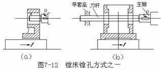
(1) The spindle of the boring machine drives the tool bar and the boring tool to rotate, and the worktable drives the workpiece to make a longitudinal feed movement, 図に示すように 7-12. The bore diameter boring in this way is generally less than about 120mm. Figure 7-12a shows the overhanging tool bar, which should not be extended too long to avoid excessive bending and deformation. Generally used to boring holes with a small depth. 図 7-12b に示すボーリングバーはより長く、ボックスの 2 つの壁の間の距離が長い同軸穴をあけるために使用されます。. ボーリングツールバーの剛性を高めるため, ツールバーの他端は中ぐり盤の後部コラムのガイドスリーブシートで支持されています.

中ぐり盤の平回転板の設定
(2) 中ぐり盤の主軸はツールバーと中ぐり工具を駆動して回転し、長手方向の送り運動を実行します。, 図に示すように 7-13. このようにして, メインシャフトのオーバーハング長は増加し続ける, それに伴い剛性も下がっていきます. 通常、短い穴をボーリングする場合にのみ使用されます.
上記2つのボーリング方法の場合, the size and tolerance of the aperture should be ensured by adjusting the length of the cutter head, 図に示すように 7-14. 調整, trial boring and measurement are required, and formal boring can only be carried out after the aperture is qualified. The technical requirements for its operation are relatively high.
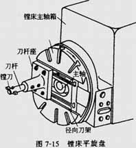
(3) The flat rotating disc of the boring machine drives the boring cutter to rotate, and the worktable drives the workpiece to make longitudinal feed motion.
図に示すように 7-15, the flat-rotating plate of the boring machine can move up and down with the headstock, and can rotate itself. The radial tool post in the middle part can do radial feed movement, and can also be in any position required.
As shown in Figure 7-16a, ラジアル刃物台を使用して、ボーリング工具を偏心位置にして大きな穴をあけます。. Φ200mm以上の穴によく使われるボーリング工法です。, ただし穴は長すぎてはいけません. 図 7-16b, 内溝穴あけ用, 平らな回転ディスクがボーリング工具を回転させます。, ラジアル刃物台はボーリング工具を駆動して連続的なラジアル送り運動を行います。. ツールの先端がツールバーの端から出ている場合, 穴の端面も穴あけ可能です.
ボーリングマシンは主に支持穴をボーリングするために使用されます。, 大中型のブラケットやボックスの内溝と端面; ボーリングマシンは穴あけにも使用できます, リーミング, フライス溝とフライス平面.
3. フライス盤のボーリング技術
横型フライス盤での穴あけは図 7-12a と同じです。. 横型フライス盤の主軸テーパ穴にボーリングバーを取り付けて回転運動させます。, ワークテーブル上にワークを設置し、横送り動作を行います。.

旋盤のフローティングボーリングツールを使用したボーリング穴
4. フローティングボーリング穴
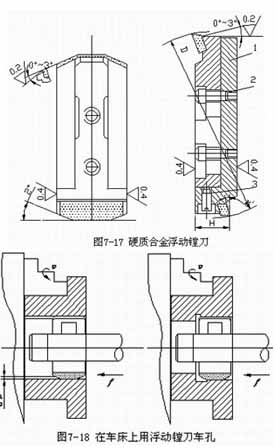
上記のように, 旋盤, ボーリング盤やフライス盤は主に片刃ボーリング工具を使用します. バッチ生産または大量生産, フローティングボーリングツールは大径穴の仕上げ加工に使用できます。 (>Φ80mm), 長い穴深さと高精度.
調整可能なフローティングボーリングブロックを図に示します。 7-17. 調整するとき, 2本のネジを緩めます 2 そしてネジを回します 3 カッターブロックの半径方向の位置を調整します 1 ボーリング穴の直径と公差に適合させるため. 図に示すように、フローティングボーリングツールが旋盤上でワークを回転させます。 7-18. 作業中, ツールバーは角型ツールホルダーに固定されています, フローティングボーリングツールブロックはツールバーの長方形の穴に取り付けられます. 2 つの刃先の半径方向の切削抵抗のバランスに基づいて、自動的に中心出しが行われます。, ツールバーへのツールブロックの取り付け誤差による穴径誤差を解消します。.
フローティングボーリングは本質的にリーマ加工と同等です, 及びその取り代, 達成可能な寸法精度と表面粗さの値はリーマ加工と同等です. フローティングボーリングのメリットは、加工品質の確保が容易かつ安定していることです。, 簡単な操作, and high productivity. しかし, the position error of the original hole cannot be corrected, so the position accuracy of the hole should be guaranteed in the previous process.
 English
 العربية
 中文(漢字)
 Čeština
 Dansk
Dansk Nederlands
 Suomi
Suomi Français
 Deutsch
 Italiano
 日本語
日本語 ಕನ್ನಡ
ಕನ್ನಡ 한국어
한국어 Português
 Русский
 Slovenčina
 Español
 Svenska
 Türkçe

