 English
 العربية
 中文(漢字)
 Čeština
 Dansk
Dansk Nederlands
 Suomi
Suomi Français
 Deutsch
 Italiano
 日本語
日本語 ಕನ್ನಡ
ಕನ್ನಡ 한국어
한국어 Português
 Русский
 Slovenčina
 Español
 Svenska
 Türkçe
工具や金型の製造では複雑な輪郭が現れる, そして量産品です. CNC工作機械が登場する前, 自動車産業で使用される鍛造金型や金型は主に手作業で製造されていました. 1970年代以降, CNC工作機械は工具や金型の製造に広く使用されています. 複雑なプロファイルの基本的な輪郭は通常、フライス加工によって処理されます。, 周囲のCNC工作機械は初期状態では3軸リンクに設定されています.
After entering the 1980s, five-axis milling machines have been widely used in complex surface processing. The contour of the workpiece after milling is very close to the final shape of the workpiece, but the last finishing process is still manual. In the late 1980s, high-speed cutting technology gradually developed and matured, 工業生産におけるその応用は、工作機械の面で継続的に改良されてきました。, 切削工具およびその他の関連技術. 高速切削により送り速度を2倍にできるため、, 生産効率を落とさずに送りピッチを小さくできる. これはワークの形状精度の向上と表面粗さの低減の前提条件となります。. 現在のところ, 高速フライス加工で加工されるワークピースのほとんどは、最後の手動加工手順を必要としません。, しかし、直接使用することもできます.
5-複雑な形状の軸加工
新しい工具素材: アルミナ系セラミックスなど, 窒化ケイ素系セラミックス, サーメット, 超硬合金, 特に超硬コーティングの継続的な開発, 硬質正面フライス加工が可能になります. 焼入れ後に金型表面をフライス加工して形状を整えることができます。, thereby avoiding deformation caused by quenching after milling. This not only simplifies the machining process, but also improves the accuracy of the workpiece.
加えて, with the application of precision forging in die manufacturing, the die blank after forging already has its designed basic shape, and the remaining machining allowance is insignificant compared with the milling of the entire blank. この場合, in addition to milling, it can also be processed by high-efficiency grinding. Compared with hard face milling, high-efficiency grinding can not only improve the shape accuracy of the workpiece, but also improve the surface roughness of the workpiece. There are many high-efficiency grinding methods, usually high-speed grinding with spherical grinding wheels and belt grinding with small-diameter belt wheels.
フライスの種類
工具や金型の 3 次元自由曲面は、通常 5 軸マシニング センターで加工されます。. ワークの材質は合金鋼や工具鋼が多いので, 工作機械の構造と数値制御システムは、加工プロセスにおける生産性とワークの精度の要件を考慮する必要があります, これに基づいて適切なレイアウトと最適化を行います。. 各種金型材料を切削する際に工作機械が過度に変形しないようにするため, 工作機械のレイアウトを決定する際には、工作機械の剛性を最優先する必要があります。. 大軸マシニングセンタ, ガントリー構造の大部分, 一部の小型5軸マシニングセンタにはハイコラム構造が採用されることもあります.
Since the beginning of the 1990s, almost all complex shapes have been processed by high-speed cutting in production. The purpose is to improve production efficiency, reduce product cost, and at the same time improve the shape accuracy of the workpiece and reduce the surface roughness. In order to meet the needs of high-speed cutting, the spindle of the machine tool almost without exception uses an electric spindle. The spindle speed is continuously variable according to the diameter of the tool used, and the speed ranges from several thousand revolutions per minute to tens of thousands of revolutions per minute. The drive system of the sliding table is also different from conventional machining centers in high-speed cutting. Commonly used system with high-speed drive nut screw assembly and linear motor drive, a maximum feed speed can reach 100m / min or more.
The appearance drawing of CNC machining complex cavity surface
When processing complex surfaces, the CNC system of the machine tool must also meet some special requirements. 例えば, CNC machining programs for complex surfaces are generally generated on CAD/CAM software. A profiled program often requires several megabytes (Byte) of storage space, and it is no longer possible to transfer NC programs with a floppy disk. したがって, the CNC system must have the function of networking with other computer systems in order to receive the CNC program directly from the CAD/CAM. 加えて, the numerical control system must also adopt advanced control technology, first of all, it requires the function of LookAhead. 言い換えると, before the machine tool processes a certain track, the data system analyzes the surface to be processed in advance. According to the curvature of each point of the curved surface and the connection relationship of each adjacent point, the feed speed of the machine tool is appropriately adjusted to achieve the highest productivity under the premise of ensuring the accuracy of the workpiece. In order to reduce dynamic errors during processing, the new servo error correcting data using a conventional tandem system is no longer proportional integral derivative (PID) controller, instead of using the state regulator by compensating for the position and speed state parameters. Using this kind of regulator can completely eliminate the drive hysteresis error, ギャップや摩擦によって生じる非線形誤差を補正します。, 工作機械の特定の振動も相殺します. ワークの形状精度の向上と面粗さの低減の要求に応えるため.
キャビティ面の切削パスの設定
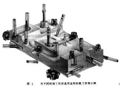
ツールシステムは、複雑なプロファイルを加工する際の生産効率と加工品質に決定的な役割を果たします。. 切削工具システムを選択する場合, まず、処理する部品の形状から開始する必要があります, さまざまな種類の切削工具を合理的に使用する. 図に示すように 1, 各パーツの形状は大きく異なります. ボールエンドミルのみで加工する場合, 小径のボールエンドミーリングカッターを選択する必要があります, 処理効率の向上が困難になる. 加えて, 一部の円弧半径が小さく、小型のボールエンドミルでも加工できない場合があります。. したがって, 生産効率とワーク形状の両方の要件を考慮して, 複雑なプロファイルを加工するには、他のタイプのフライスを 5 軸マシニング センターに装備する必要があります, エンドミルや三面フライスなど.
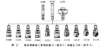
形 2 いくつかのタイプのフライスを示します. サイズが許す限り, 工具の形状に関係なく, 刃先はコンバーチブルクランプを備えたフライスインサートである必要があります. このようなナイフは、刃と本体の組み合わせによりさまざまな方法で組み合わせることができます。, ブレードとボディは別の会社で製造することもできます. したがって, 大規模な専門生産を形成することができます, これはツールの品質を向上させるだけでなく、, だけでなく、ツールの製造コストの削減にも役立ちます.
現在, 市場に出ている刃先交換式ブレードのほとんどは、CVD コーティングされた超硬ブレードを使用しています。. より高い擬似耐摩耗性を実現するために, 刃先交換式インサートはすべて多層コーティングです. Bizhi Al2O3 はブレードの化学的安定性を向上させることができます. TiN、TiCNにより刃の耐摩耗性が向上します。. 刃の切れ味を高めるために, 低温CVD法に加えて, コーティングはPVD法でも製造可能です. 一部の加工ではブレードに非常に厳しい要件が課されます. 仕上げ面の粗さを低減するために、ブレードには鋭い切れ刃が必要です, but also have a high wear resistance to ensure the shape accuracy of the workpiece. この場合, a combination of multiple coatings must be used. In order to ensure that the use of some blades is foolproof, the number of coating layers can be as high as 100.
The life of the tool is closely related to the feed rate, cutting speed and depth of cut. The optimal cutting amount is often a small range, which should be determined according to the specific tool and workpiece material.
加えて, cutting strategies such as: The planning of the tool path, the normal vector of the tool axis surface (the normal direction of the surface at this point) or the different methods along the surface tangent vector (the tangent direction of the surface at this point), 等, are also a key factor for processing complex surfaces . 加工ワークの表面粗さに影響を与えるだけではありません, ワークの形状や寸法精度にも影響します. 形 3 円筒面を加工するときに使用されるさまざまな切削方法を示します。. 円周方向切削用, 工具経路は 2 軸リンクで補間する必要があります. 母線方向に沿って切断する場合, ツールは単軸補間を実行するだけで済みます。. 加えて, 切削方法が異なると工具の摩耗に大きな違いが生じます. ダウンミーリング時の工具摩耗はアップミーリングよりも大幅に低い, 往復フライス加工中の摩耗は、一方向フライス加工の摩耗よりもはるかに大きくなります。.
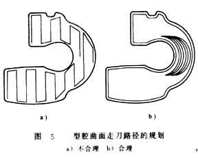
加工工程の安定性を向上させるため, 切断戦略を最適化する場合, 切断の連続性を確保する必要があります, 切削時間を短縮するには、切削動作と空ストロークを可能な限り減らす必要があります。. 鋼の荒加工の場合, 継続的な上昇ミリングを確保する必要がある, 切断時の刃のピークを最小限に抑える変動量.
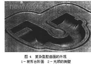
図のようなワークを加工する場合 4, 図 5a に示す列カット軌跡セクション処理を使用した場合; ツールの動きが非常に無理がある, 切断条件が非常に不十分です, 処理時間は33分です, ワークピースの表面粗さは6〜9μmです. 図 5b に示す円切断パスに切り替えて処理すると、, 処理時間は約です 27 分. 同時に, ワークの粗さも小さくすることができます。 2 ~4μm.