 English
 العربية
 中文(漢字)
 Čeština
 Dansk
Dansk Nederlands
 Suomi
Suomi Français
 Deutsch
 Italiano
 日本語
日本語 ಕನ್ನಡ
ಕನ್ನಡ 한국어
한국어 Português
 Русский
 Slovenčina
 Español
 Svenska
 Türkçe
Il sistema di fresatura ad alta velocità è un sistema dinamico complesso, che è soggetto a vibrazioni durante la lavorazione di parti sottili. Il flutter è una vibrazione relativa molto forte tra l'utensile e il pezzo durante il processo di fresatura. Questo tipo di vibrazione distruggerà la corretta posizione relativa dell'utensile e del pezzo, e ridurre la qualità della lavorazione della superficie e l'efficienza della fresatura. Per molto tempo, le vibrazioni da taglio sono state uno dei principali argomenti di ricerca nel settore della produzione di macchinari e nella lavorazione di fresatura. The research on cutting chatter involves a wide range of contents. In this paper, a certain research on the flutter model, including the nonlinear mathematical model and stability conditions; Su questa base, MATLAB/SIMULINK software is used to carry out a certain simulation study on the generation and control of chatter, including the adjustment strategy of milling parameters (spindle speed, feed, tool angle, eccetera.).
There is relative movement between the tool and the workpiece, and the excess material of the workpiece is removed by the action of the cutting edge and the knife face.
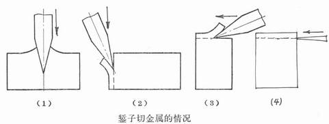
Allowance on the milled workpiece
Figura 1, the allowance of the chisel milled on the workpiece
Come mostrato in figura 1, the milling edge plays the role of “cutting” and “milling”, and the cutter face plays the role of “pushing”.
“Cut”-the workpiece has no motion component relative to the cutting edge.
“fresatura”-the workpiece has a motion component relative to the cutting edge.
“squeeze”-mainly the squeeze of the rake face, but also a certain amount of squeeze on the flank face.
The margin of removal of the workpiece is the result of the combined effect of the above three. Due to the high strength of the material being cut, the knife has a large wedge angle and cannot be very thin. IL “push” function consumes a large share of energy;
And “cutting” E “fresatura” play an important role in separating the cut material and forming the machined surface.
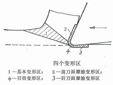
Four deformation zones during milling
Figura 2. Four deformation zones of the part
Come mostrato in figura 2, 1 is the basic deformation zone of the part;
2 is the frictional deformation zone of the rake face;
3 is the frictional deformation zone of the flank surface;
4 is the front deformation zone. Zone 1 and Zone 2 consume the main part of power, while Zone 3 and Zone 4 play an important role in forming the processed surface.
If the cutting edge is very sharp, zone 4 is very small;
If the tool clearance angle is large, zone 3 is also small.
Zone 1 is the main deformation zone. If the cutting speed is high, zone 1 becomes very narrow and almost becomes a surface (a line as shown in Figure 4), which is called a shear surface. The angle between the direction of the shear surface and the aspect of the cutting speed is the rake angle Φ.
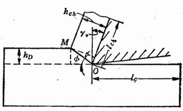
Shear surface and deformation coefficient during milling
Figura 3. Shear surface and deformation coefficient
The approximate value of shear angle φ can be calculated by the following formula:
M. E. Merchant formula
Φ=π/4-β/2+γo/2
Lee and Shaffer (Lee and Shaffer) formula
Φ=π/4-β+γo
In the formula, β is the friction angle between the rake face and the chip, and γo is the rake angle.
When the milling speed is increased very high, the material to be cut will not have time to fully deform, the shear angle Φ increases, the amount of deformation decreases, and the milling force also decreases. After the milling speed is increased, the friction coefficient between the front and flank faces and the chip and the workpiece is reduced, which is also conducive to the reduction of the milling force.
There is a simple way to measure material deformation, questo è, to calculate the “deformation coefficient” through measurement. It was called “shrinkage factor” in the past, and the two are the same thing.
Come mostrato in figura 3, the original length of the milled layer is lc, and the length after forming chips is lch, then the deformation coefficient Λh=lc/ lch
In the process of milling, the material of the cut layer turns into chips, which undergoes shear slip. According to the principles of material mechanics, it is more scientific to measure the degree of deformation of a material by the amount of shear strain. There is a certain relationship between the shear strain ε and the deformation coefficient. After calculation,
Ε=ΔS/Δy=cosγ0/[sinφ?cos(φ-γ0)]
=ctgφ+tg(φ-γ0)
=(Λh2-2Λh?sinγ0+1)/(Λh?cosγ0)
In the formula, γo is the rake angle of the tool.
Λh and ε increase, it means that the material deformation is large;
vice versa.
Obviously, during high-speed milling, both Λh and ε decrease, and the milling force decreases.
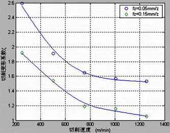
Perform high-speed milling deformation coefficient tests of 45 steel and aluminum alloy 5A02. Suppose: the tool is a cemented carbide end mill with φ20mm, Cutting ap=0.5~1mm, The feed amount is fz=0.05~0.15mm/z, Cutting speed v=251~1256m/min. The test results are shown in Figure 5 and Figure 6.
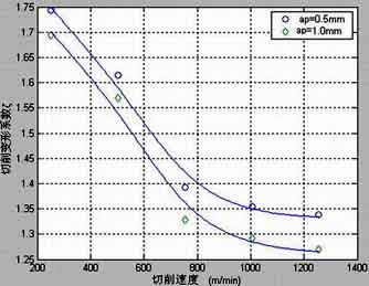
Deformation coefficient of 45 steel during high-speed milling
Figura 4 Deformation coefficient of high-speed cutting 45 acciaio
Deformation coefficient of aluminum alloy 5A02 during high-speed milling
Figura 5 Deformation coefficient of high-speed cutting aluminum alloy 5A02
It can be seen from the figure that when the cutting speed increases, the deformation coefficient decreases significantly.