 English
 العربية
 中文(漢字)
 Čeština
 Dansk
Dansk Nederlands
 Suomi
Suomi Français
 Deutsch
 Italiano
 日本語
日本語 ಕನ್ನಡ
ಕನ್ನಡ 한국어
한국어 Português
 Русский
 Slovenčina
 Español
 Svenska
 Türkçe
Con l'aumento della progettazione superficiale complessa delle parti nell'industria moderna, 5-la lavorazione degli assi rappresenterà una percentuale crescente della lavorazione CNC. Poiché la lavorazione CNC a 5 assi aggiunge due gradi di libertà di rotazione, aumenta la difficoltà di calcolo della simulazione del movimento della lavorazione CNC e del controllo dell'interferenza dell'utensile, soprattutto quando si lavorano pezzi con forme estremamente complesse. Perciò, in order to ensure that the five-axis CNC machine tool performs high-efficiency and high-quality milling processing, the development of five-axis machining tool path generation and interference checking software will become a major issue for researchers.
proposed a feature projection method suitable for five-axis CNC machining tool interference processing, which is to discretize the machined surface into a series of surface feature points. Whether the tool interference occurs can be judged by whether the feature point enters the inside of the tool surface. Allo stesso tempo, the machined curved surface and the tool surface are projected onto a specific plane, e solo i punti di rilevamento delle caratteristiche nell'area della superficie curva, inclusa la grafica di proiezione dello strumento, sono soggetti al controllo delle interferenze, che migliora l'efficienza del rilevamento delle interferenze.
1. Metodo di controllo delle interferenze
Sistema di coordinate e trasformazione delle coordinate
Istituzione del sistema di coordinate a 5 assi
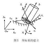
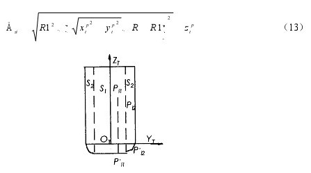
Come mostrato in figura 1, il sistema di coordinate locali L per la lavorazione NC della fresa circolare a cinque assi è rappresentato come asse XL, Asse YL e asse ZL. L'asse YL punta sempre verso la direzione di taglio f del contatto dell'utensile (Punto CC in breve) OL, e l'asse ZL punta verso la direzione normale all'esterno della superficie n. L'asse XL è determinato dalla regola della mano destra dell'asse YL e dell'asse ZL. L'utensile generalmente ruota attorno all'asse XL dall'asse ZL all'asse YL di un angolo di anticipo (heel angle) UN, and rotates around the ZL axis one by one slip angle b. Inoltre, the tool coordinate system T (XT, YT, ZT) can also be defined at the tool location point (CL point for short) OT. Wherein YT axis pointing point and CC-dot chain line CL direction, ZT axis direction of tool axis vector, XT axis direction is determined by the right hand rule and YT ZT axis of the shaft. The coordinate origin is at the tool center point (ie CL point) OT. In order to simplify the interference check, the tool surface with a relatively regular shape is used as the reference for interference check. The processed surface is discretized to express the surface shape in the form of a set of characteristic points. The original data of these feature points are expressed in the world coordinate system W, so the feature point data must first be transformed from the world coordinate system W (OW-XW, YW, ZW) to the local coordinate system L (OL-XL, YL, ZL) ). It is then transformed from the local coordinate system L to the tool coordinate system T (OT-XT, YT, ZT).
Interference inspection method for 5-axis ring cutter machining
Metodo di controllo delle interferenze
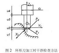
If the tool and power head have been selected, the size of the tool system (tool and power head) is known. Whether the tool system interferes with the machined surface can be determined by judging whether the feature point P enters the tool surface. Come mostrato in figura 2, it is the positional relationship between the tool system and the machined surface when the ring knife is processed. In the tool coordinate system, let the coordinate of the characteristic point P be PI (Xpt, Ypt, Zpt). According to the different combination parts of the tool system, the coordinate value Zpt of the characteristic point P is divided into 4 sections for judgment. Details are as follows:
When the feature point P is within the range of u1, no interference will occur.
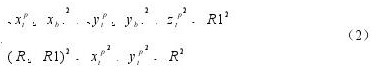
When the characteristic point P is in the range of u2, there are two situations, the torus is divided into two parts: the small cylindrical part P1 and the circular part P2. When the feature point is involved in the cylindrical part P1, tool interference occurs, questo è,
where R represents the radius of the tool, and R1 represents the radius of the ring of the circular tool.
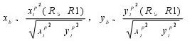
When the feature point is involved in the ring part P2, tool interference also occurs, which is satisfied
5 axis milling tool interference calculation formula
in the style
5-axis machining interference calculation formula
If the feature point P does not enter the P1 and P2 parts, no tool interference will occur.
When the characteristic point P is within the range of u3, when the distance between the characteristic point P and the ZT axis is less than the tool radius, tool interference occurs, which is satisfied
Otherwise, no tool interference will occur.
When the feature point P is in the range of u4, the situation is the same as that of 3, as long as the tool radius R in equation (3) is replaced by the power head radius d/2 to make the judgment.
The feature points of the curved surface that interfere with the tool system are called interference points. Detect all the interference points according to the above method, and calculate the amount of interference in the radial direction of each interference point, and then use an appropriate method to eliminate the interference.
Feature Projection Method for Interference Inspection
Project the tool system and the feature points of the curved surface onto a two-dimensional plane (projection plane), and divide the machined surface into a series of squares by taking a reasonable distance on the two-dimensional projection plane. Come mostrato in figura 3, when the square is completely covered by the contour of the projected tool system, it is recorded as a complete square. The surface feature points in this area may interfere with the tool system;
When the square is not intersected by the contour of the projected tool system at all, it is recorded as a non-square and it is impossible to interfere with the tool system;
When the square part is covered by the contour of the projected tool system, it is recorded as a partial square. In order to further reduce the number of feature points inspection, a quadtree segmentation process is performed on part of the squares, non-squares are deleted, and the feature points that may interfere with each other are re-edited in the order of regions, and then the coordinate transformation and interference inspection are performed.
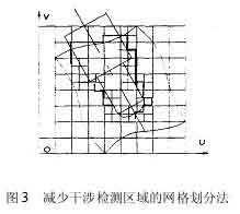
Net division method for reducing interference detection area in NC machining
2. Interference elimination method:
Rotating tool axis
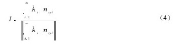
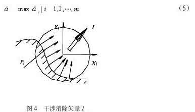
At a tool location point, there are m surface feature points that interfere with the tool system. Considering the interference situation of m interference points comprehensively, è possibile trovare una direzione ottimale per eliminare l'interferenza per eliminare l'interferenza dell'utensile nel modo più efficace. Per questa ragione, un nuovo concetto di “piano di cancellazione delle interferenze” è introdotto. Proiettare i vettori normali alla superficie in m punti di interferenza sul piano XTYT del sistema di coordinate utensile T. Supponiamo che la proiezione del vettore normale alla superficie nel punto di interferenza sul piano XTYT sia nxyi (io=1, 2, …, M), e la componente di interferenza del punto di interferenza sul piano XTYT è Dt (io=1, 2, …, M) . Come mostrato in figura 4, il vettore di cancellazione dell'interferenza I può essere ottenuto da
Metodo di rilevamento delle interferenze dell'asse rotante dell'utensile
Dopo il vettore di cancellazione dell'interferenza I (Sx, Si, Taglia) è calcolato dalla formula (4), il vettore di cancellazione delle interferenze I e l'asse ZT formano il piano di cancellazione delle interferenze. Sia K il vettore prodotto vettoriale dell'asse ZT e il vettore di eliminazione I. Su un piano parallelo a “piano di eliminazione delle interferenze”, l'angolo di eliminazione delle interferenze d che calcola quanto è inclinato l'utensile attorno all'asse K posso semplicemente eliminare l'interferenza dell'utensile. Come mostrato in figura 5. Supponendo che il punto di interferenza Pi (io=1, 2,…, M) è escluso dalla superficie del sistema di utensili, l'angolo minimo richiesto è di (io=1, 2,…, M). Allora l'angolo di cancellazione dell'interferenza d è il valore massimo di tutti gli angoli di
Metodo vettoriale di cancellazione delle interferenze
Per escludere il punto di interferenza Pi dal sistema utensile, il punto di interferenza Pi è fisso, e il sistema di utensili ruota attorno all'asse K nella direzione I. It is equivalent to the angle of rotation di of the interference point Pi relative to the tool system and the tool coordinate system in the plane of the parallel interference elimination plane IOTZT. Take the ring knife as an example to analyze.
Come mostrato in figura 5, the rotation axis of the tool system passes through the center point O1 of the arc of intersection of the elimination plane IOTZT and the toroidal surface of the tool, and is parallel to the vector K, passes the interference point Pi, and is parallel to the elimination plane IOTZT. As a section plane, the intersection line between the section plane and the torus of the tool is a quartic curve, and the intersection line with the cylindrical surface is two straight lines. There are two situations in which the axis of the ring knife rotates. When the interference point Pi falls into the circular knife cylinder, the rotation angle di is ∠PiOPi’ (Figure 5a), and the calculation formula is
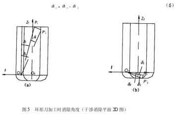
Eliminate interference angle during ring cutter processing
and the angle d1 is calculated as follows
At that time, the point Pi intersects the cylindrical surface section line during the rotation, and the calculation formula for d2 is
When the point Pi does not intersect the cylindrical section line during the rotation, the point Pi’ may intersect the quartic curve of the circular section or the section line of the bottom plane of the tool. The calculation of the angle d2 is more complicated when it intersects the quartic curve of the circular section. Per semplificare il calcolo, l'angolo di rotazione viene trattato in modo conservativo. In questo momento, l'angolo calcolato d2 è maggiore dell'angolo effettivo, ma non ha alcun effetto sull'elaborazione delle interferenze dello strumento. I punti di lavorazione conservativa Pi’ vengono tutti ruotati per intersecare il piano inferiore dell’utensile, e l'angolo d2 è uguale a
Come mostrato in figura 5(B), quando il punto di interferenza Pi cade nell'anello del coltello circolare, anche l'angolo di rotazione viene trattato in modo conservativo. I punti Pi' vengono tutti ruotati per intersecare il piano inferiore dell'utensile, the rotation angle di is ∠PiOPi’, e la formula di calcolo è la stessa dell'equazione (6), dove gli angoli d1 e d2 si calcolano come segue
Quando si alza il coltello, il punto di interferenza interseca la superficie dell'arco del filo del coltello
Quando il denominatore nella formula (11) è minore del numeratore, the point Pi’ cannot intersect the bottom plane of the tool during the rotation. In questo momento, the interference cannot be eliminated by rotating the tool axis, but the possibility of this situation is extremely small.
The same principle can handle the interference points in the cylinder of the power head.
Although the tool system can eliminate the interference points by rotating the d angle to the I direction, the tool system may interfere with other surface feature points during the rotation. Perciò, after the tool system is rotated, a new tool axis vector must be calculated and a new tool coordinate system must be re-established. Then check the interference with the curved surface. When the interference phenomenon cannot be eliminated by rotating the tool axis, the tool lifting method along the tool axis is used to eliminate it.
knife lift method
When using the method of lifting the tool along the tool axis to eliminate interference, the amount of tool lifting along the ZT direction should be calculated. For m interference points Pi (io=1, 2, …, M). Calculate the tool lift amount Dzi (io=1, 2,…, M) excluded from each interference point, and also take the largest amount as the tool lift amount Dz.
Come mostrato in figura 6. When using a ring knife for CNC machining, there are two ways to calculate the amount of tool lift. When the interference point Pi falls into the tool cylinder S1 with a radius of (R-R1), the tool lifts up, and the interference point finally intersects the bottom plane of the tool. The lifting amount is calculated as
When the interference point Pi falls within the ring body S2 with a radius difference of R1, the interference point intersects with the arc surface of the blade when the tool is lifted, and the lift amount is:
(1) Determine the CC point of the curved surface, the normal vector n and the tool passing vector f, calculate the CL point of the tool, establish the corresponding coordinate system, and calculate the initial tool axis vector Ti (io=1, 2, …, n);
(2) For a tool location point, select a specific plane, and project the tool system and the machining surface onto the plane;
(3) The processing surface is divided into a network on the projection plane to obtain a series of square regions. Use the tag Tag to indicate the nature of the square. When Tag=1, it is a complete square and accept; When Tag=2, it is non-square and discarded; When Tag=3, it is a partial square, and a quadtree division is required to discard non-squares;
(4) Arrange the surface feature points in the complete square and part of the square area obtained after segmentation in the order of the area, reprogram them into a detection file, and perform coordinate transformation of these feature points Pi from the world coordinate system W to the tool coordinate system T;
(5) In the tool coordinate system T, divide the coordinate value of the characteristic point Pi (xipp, yip, zipp) into segments to determine whether the point falls within the surface of the tool system. If it falls, interference occurs, go to the next step; If no interference occurs, go to 10;
(6) Need to raise the knife to eliminate interference, turn 9; In other cases, utilizzare il metodo dell'asse dell'utensile rotante per eliminare le interferenze, go to the next step;
(7) Determinare il piano di eliminazione delle interferenze e calcolare l'angolo di rotazione di per eliminare le interferenze;
(8) Calcolare il nuovo vettore dell'asse utensile Ti', determinare la nuova coordinata utensile T’, ripetere i passaggi 4 E 5 per determinare se il metodo dell'asse dell'utensile rotante può eliminare l'interferenza. Se può essere eliminato, go to 10; Se non può essere eliminato, passare al passaggio successivo;
(9) La quantità di sollevamento dell'utensile Dzi nella direzione dell'asse dell'utensile, utilizzare il metodo di sollevamento utensile per eliminare le interferenze, e registrare il numero di serie del punto di posizione dell'utensile per l'elaborazione supplementare dopo lo spostamento dell'utensile;
(10) Giudica se è l'ultimo punto di posizione dell'utensile, se non è, quindi prendi un punto di posizione dello strumento e trasferiscilo 2;
Emettere il risultato del test e terminare.
3. Implementazione dell'algoritmo
Progettazione di lavorazioni CNC a 5 assi di superfici curve complesse
Lavorazione CNC a cinque assi di superfici curve complesse
Il metodo di elaborazione dell'interferenza è proposto per la situazione della lavorazione CNC con fresatura a cinque assi. E dal metodo di elaborazione delle interferenze e dalla riduzione dell'area di rilevamento, due aspetti per semplificare il processo di elaborazione delle interferenze. Si propone che la superficie del sistema di utensili venga utilizzata come standard di rilevamento, e la superficie lavorata viene discretizzata in una serie di punti caratteristici della superficie. Il problema del controllo dell'interferenza dell'utensile in uno spazio tridimensionale così complesso viene semplificato in un semplice problema di calcolo del piano. Allo stesso tempo, per eliminare più efficacemente le interferenze degli utensili, viene determinato un piano di eliminazione delle interferenze in base alla situazione di interferenza. Inoltre, by projecting the tool system and the feature points of the curved surface onto a specific plane and dividing the projection plane into a network to delete some irrelevant detection areas, the calculation time can be greatly shortened. This method can be used for the ball head cutter, cut bite interference and collision interference at the flat annular cutter knives and processed, the algorithm is stable, easy to implement.