Perché la tornitura del filo è così impegnativa?
I requisiti per la tornitura di filetti sono più elevati rispetto alle normali operazioni di tornitura. La forza di taglio è generalmente più elevata, e il raggio dell'estremità tagliente dell'inserto filettato è più piccolo e più debole.
Nell'elaborazione del thread, la velocità di avanzamento deve corrispondere esattamente al passo della filettatura. Per un passo di 8 fili/pollice (tpi), the tool must advance at a feed rate of 8 revolutions/inch or 0.125 inches/revolution. Compared with ordinary turning applications (where the typical feed rate is about 0.012ipr), the feed rate of thread turning is 10 times higher. The force at the tip of the threaded processing insert may be 100 A 1,000 times higher.

Thread turning with multi-tooth thread insert
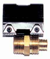
figura 2: Multi-tooth inserts, with multiple thread teeth in a series, thread processing efficiency may be improved, but the cutting force is higher.
The end radius that bears this force is generally 0.015 pollici, while the radius of a conventional turning insert is 0.032 pollici. For threaded tools, the radius is strictly limited by the root radius of the permitted thread shape (its size is specified by the relevant thread standard). It is also limited by the required cutting action, perché il materiale non può sopportare il processo di taglio nella tornitura ordinaria, altrimenti si verificherà una deformazione del filo.
Il risultato di una forza di taglio più elevata e di un intervallo di concentrazione della forza più ristretto è: Gli inserti per la lavorazione di filetti sopportano sollecitazioni molto più elevate rispetto agli utensili di tornitura generali.

Filo di tornitura con metodo di alimentazione a taglio incrociato
Confronto tra lame a profilo parziale e completo
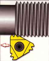
Inserti di profilo parziale, a volte indicato come “non sormontato” inserti, tagliare le scanalature del filo senza creare creste o creare creste sul filo. (Guarda la figura 1) Uno strumento può produrre una serie di thread, fino alla pece più spessa, cioè, il minor numero di fili per pollice, consentito dalla resistenza del raggio dell'estremità della lama.
Il raggio finale è progettato per essere sufficientemente piccolo da consentire alla lama di elaborare passi diversi. Per filettature a passo piccolo, the end radius will appear to be too small. This means that the blade must penetrate deeper when machining. Per esempio, machining an 8 tpi thread with a partial profile insert requires a thread depth of 0.108 pollici. The same thread produced with a full profile blade requires only a specified depth of 0.81 pollici. Perciò, the full profile insert can produce a stronger thread. Inoltre, the operation of machining threads with full profile inserts can be done in 4 less steps.

Thread cutting by flank transverse cutting method
Multi-tooth blade
The multi-tooth blade has a series of teeth continuously, and the cutting depth of any tooth in the thread groove is deeper than the previous tooth. (Guarda la figura 2) With these inserts, the number of operations required to machine a thread can be reduced by 80%. The tool life is much longer than single-center inserts, because the final tooth only processes half or one-third of the metal of a given thread.
Tuttavia, due to their high cutting force, it is not recommended to use these inserts for the processing of thin-walled parts-because chatter may occur. Inoltre, the structure for machining workpieces with these inserts must have sufficient thread clearance so that all teeth can exit cutting.

Turning thread by adjusting blade helix angle
Figura 3: The choice of cross-cutting feed method has a great influence on thread processing efficiency

Custom thread cutting tool for milling threads
Figura 4: Flank transverse cutting does not produce V-shaped chips, but produces chips similar to those in ordinary turning.
Feed per thread
The cutting depth of each pass, or the feed of each thread, is very critical in thread processing. Each connected operating channel must engage the larger part of the cutting edge of the blade. If the feed per pass is constant (this method is not recommended), the cutting force and metal removal rate will increase drastically from the previous pass to the next.
Per esempio, when using a constant feed of .010 pollici / processing speed of a channel 60 ℃ thread shape, the second track material is removed 3 times the first track. As with each subsequent operation, the amount of metal removed continues to rise exponentially.
In order to avoid this increase in the amount of removal and maintain a more realistic cutting force, the thread depth should be reduced with each operation.
Cross-cut thread feed method
There are at least four thread crosscut feeding methods. (Guarda la figura 3) Few people have discovered how much impact one of these methods has on the effectiveness of threading operations.
• Radial thread crosscut feed
•Although this may be the most commonly used method for thread processing, it is indeed the least recommended method. Since the tool is fed radially (perpendicular to the centerline of the workpiece), the metal is removed from both sides of the thread flank, resulting in V-shaped chips. Such chips are difficult to break, so the flow of chips is a problem. Inoltre, due to the higher heat and pressure on both sides of the blade end, the tool life is usually shorter than other cross-cutting feed methods.
• thread flank cross feed
In this method, the transverse direction is parallel to one of the flank of the thread, ciò significa generalmente che l'utensile avanza in linea retta a 30°C. I trucioli sono simili a quelli prodotti nella tornitura ordinaria. (Guarda la figura 4.) Rispetto al taglio trasversale radiale, i trucioli prodotti con questo metodo sono più facili da modellare e vengono facilmente scaricati dal tagliente, con una migliore diffusione termica. Tuttavia, in questo metodo di alimentazione trasversale, il bordo d'uscita della lama sfrega contro il fianco del dente e non taglia. Questo brucerà i thread, con conseguente scarsa ruvidità superficiale e persino vibrazioni.
• Avanzamento di taglio trasversale del fianco del dente del filetto modificato (consigliato)
Questo metodo è simile al metodo di avanzamento del taglio trasversale del fianco della filettatura, tranne che l'angolo di taglio trasversale è inferiore all'angolo della filettatura, cioè, meno di 30 ℃. Questo metodo conserva i vantaggi del metodo di taglio trasversale del fianco della filettatura, evitando i problemi causati dal bordo d'uscita della lama. Un angolo di taglio trasversale di 291/2 ℃ generalmente produce i migliori risultati, ma nel funzionamento reale, è accettabile un angolo di taglio trasversale compreso tra 25 e 291/2 ℃.
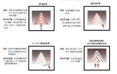
Figura 5: Regolando l'angolo dell'elica della lama, come il “inclinato” lama a destra, l'angolo di spoglia sotto i bordi anteriore e posteriore della lama può essere bilanciato, che può produrre un'usura più uniforme.
• Avanzamento di taglio trasversale del fianco del filo alternato
Questo metodo avanza alternativamente lungo i due fianchi del filo, quindi utilizza i due fianchi della lama per formare il filo. Questo metodo può garantire una maggiore durata dell'utensile, perché vengono utilizzati entrambi i lati dell'estremità della lama. But it can also cause chip flow problems —
This problem may affect the surface roughness and tool life. This method is usually only used for large pitch and (imperial) trapezoidal and oblique quadrilateral threads.
Clearance thread angle compensation
Certain thread machining inserts and tool holder systems have the ability to accurately tilt the insert in the cutting direction by changing the helix angle. This feature can produce higher-quality threads because it prevents the blade from rubbing against the flank of the thread. It can also provide longer tool life because the cutting force is evenly distributed over the entire length of the cutting edge.
There is no cutting insert that is inclined in this way- The way to make the cutting edge parallel to the centerline of the workpiece- An unequal clearance angle will be formed under the leading edge and trailing edge of the blade. (Guarda la figura 5) Especially for thicker pitches, this disparity may cause friction in the tooth flank.
The adjustable system allows the angle of the blade to be tilted through the positioning of the tool chuck (usually with shims). Precise adjustment will achieve similar leading and trailing edge angles, ensuring uniform development of blade wear.
Figura 6: This custom thread cutting tool is used to machine two independent threads on a six-spindle lathe. In the past, threads were processed one at a time. The insert used here was actually originally intended for thread milling cutters, but it is used here as a turning insert
Miniaturization and specialization of thread cutting inserts
Utensili a inserti indicizzabili per la tornitura di filettature interne su fori con un diametro di circa 0.3 pollici sono ora disponibili sul mercato.
Ci sono molti vantaggi nel realizzare fori così piccoli nelle filettature mediante tornitura. La qualità del filo da lavorare è solitamente relativamente elevata, la struttura della lama consente la fuoriuscita dei trucioli dal foro e raramente danneggia la filettatura, e la lama può essere indicizzata, quindi il costo dello strumento è basso.
I gradi di metallo duro utilizzati in queste applicazioni sono generalmente quelli che consentono la lavorazione a velocità superficiali inferiori. Per la lavorazione di filetti interni in fori piccoli, i limiti delle macchine utensili sono generalmente problemi diversi dalle basse velocità superficiali.
I progressi tecnologici compiuti dalle persone hanno ampliato il campo di applicazione degli utensili per tornitura di filetti, and the turning of internal threads into small holes is one example. Tuttavia, despite the expansion of the scope of application of standard tools, manufacturers still have to encounter specific problems, which creates room for the existence of customized tools. (Guarda la figura 6) The special tool developed in cooperation with the tool supplier is an option that cannot be ignored when searching for the correct threading tool for a specific job.
 English
 العربية
 中文(漢字)
 Čeština
 Dansk
Dansk Nederlands
 Suomi
Suomi Français
 Deutsch
 Italiano
 日本語
日本語 ಕನ್ನಡ
ಕನ್ನಡ 한국어
한국어 Português
 Русский
 Slovenčina
 Español
 Svenska
 Türkçe

