catégories de produits
Mots clés du produit
Montage et réglage des outils des pièces de tournage de tours
Serrage des outils de tournage
1) La tige de l'outil de tournage ne doit pas dépasser trop longtemps du porte-outil, et la longueur générale ne doit pas dépasser 1.5 multiplié par la hauteur de la tige de l'outil (sauf pour tourner les trous, rainures, etc.)
2) La ligne centrale de la barre d'outils de l'outil de tournage doit être perpendiculaire ou parallèle à la direction de coupe..
3) Réglage de la hauteur de la pointe de l'outil:
General technical code for turning metal processing (JB/T9168.2-1998)
Serrage des outils de tournage
1) La tige de l'outil de tournage ne doit pas dépasser trop longtemps du porte-outil, et la longueur générale ne doit pas dépasser 1.5 multiplié par la hauteur de la tige de l'outil (sauf pour tourner les trous, rainures, etc.)
2) La ligne centrale de la barre d'outils de l'outil de tournage doit être perpendiculaire ou parallèle à la direction de coupe..
3) Réglage de la hauteur de la pointe de l'outil:
(1) When turning the end face, turning taper surface, tourner le fil, turning forming surface and cutting solid workpieces, the tool tip should generally be the same height as the axis of the workpiece.
(2) Rough turning of the outer circle, fine turning of the hole, and the tool tip should generally be slightly higher than the axis of the workpiece.
(3) When turning slender shaft pins, rough turning holes, and cutting hollow workpieces, the tool tip should generally be slightly lower than the axis of the workpiece.
4) The bisector of the nose angle of the thread turning tool should be perpendicular to the axis of the workpiece.
5) When clamping the turning tool, the shims under the tool bar should be small and flat, and the screws for pressing the turning tool should be tightened.
Clamping of turning hardware parts
1) When using a three-jaw self-centering chuck to clamp a workpiece for rough turning or finishing turning, if the diameter of the workpiece is less than 30 mm, the overhang length of the workpiece should not be greater than 5 times the diameter. If the diameter of the workpiece is greater than 30 mm, the overhang length of the workpiece should not be greater than 3 times the diameter.
2) When using four-jaw single-action chuck, faceplate, angle iron (bent plate), etc.. to clamp irregular and heavy workpieces, a counterweight must be added.
3) When machining shaft pin workpieces between thimble fixtures, adjust the tailstock center axis to coincide with the lathe spindle axis before turning.
4) When machining a slender shaft between two thimble fixtures, the tool holder or center holder should be used. Pay attention to adjusting the top tightening force during processing, and the dead center and center frame should be lubricated.
5) When using the tailstock, extend the sleeve as short as possible to reduce vibration.
6) When clamping a workpiece with a small supporting surface and high height on a vertical car, use a raised jaw and add a tie rod or a pressure plate to the appropriate position to compress the workpiece.
7) When turning wheel and sleeve castings and forgings, they should be aligned according to the unprocessed surface to ensure uniform wall thickness after processing.
Turning process of hardware parts
1) When turning the stepped shaft of the turning table, in order to ensure the rigidity during turning, generally the position with the larger diameter should be turned first, and the position with the smaller diameter should be turned later.
2) When grooving the workpiece on the shaft, it should be performed before finishing to prevent deformation of the workpiece.
3) When finishing turning a threaded shaft, generally you should finish turning the unthreaded position after threading.
4) Before drilling, the end face of the workpiece should be turned flat. Si nécessaire, drill the center hole first.
5) When drilling deep holes, generally drill pilot holes first.
6) En tournant (Φ10—Φ20) ㎜ holes, the diameter of the tool bar should be 0.6—0.7 times the processed hole diameter;
When machining holes with a diameter greater than Φ20mm, generally the tool holder with the turning head should be used.
7) When turning multiple threads or multiple worms, try cutting after adjusting the gears.
8) When using an automatic lathe, adjust the relative position of the tool and the workpiece according to the adjustment card of the machine tool. After the adjustment is completed, test turning is required, and the first part can be processed only after it is qualified;
Pay attention to tool wear and workpiece size and surface roughness at any time during processing.
9) When turning on a vertical lathe, after the tool post is adjusted, the beam cannot be moved at will.
10) When the relevant surface of the workpiece has position tolerance requirements, try to complete the turning in one clamping.
11) When turning the cylindrical gear blank, the hole and the reference end face must be processed in one clamping. Si nécessaire, a marking line should be drawn near the gear index circle on the end face.
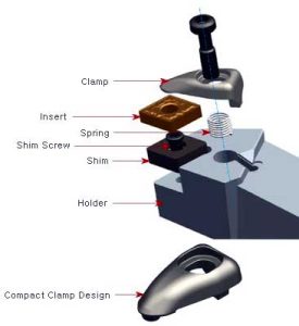
Clamping method of turning tool
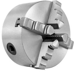
Mandrin auto-centrant à trois mors pour serrer et tourner la pièce
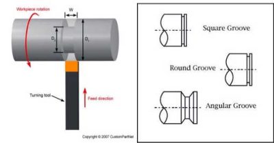
Ways of turning stepped shafts
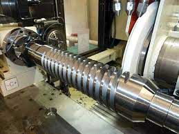
Finish turning threaded shaft
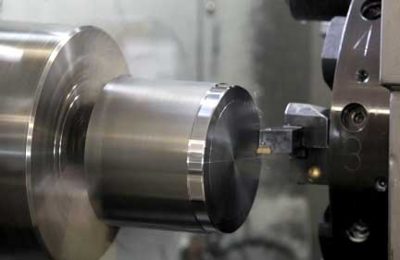
Smooth turning of the end face of the workpiece
Contactez-nous
En attente de votre email, nous vous répondrons dans les 12 heures avec des informations précieuses dont vous aviez besoin.
 English
 العربية
 中文(漢字)
 Čeština
 Dansk
Dansk Nederlands
 Suomi
Suomi Français
 Deutsch
 Italiano
 日本語
日本語 ಕನ್ನಡ
ಕನ್ನಡ 한국어
한국어 Português
 Русский
 Slovenčina
 Español
 Svenska
 Türkçe


