Qu'est-ce que le fraisage? Quel est le processus de fraisage? Quelles pièces peuvent être usinées par fraisage CNC? Quelle précision les pièces d'usine chinoises peuvent-elles atteindre?
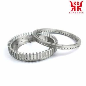
Qu'est-ce que le fraisage?
Pièces fraisées CNC
Comment sont fabriquées les pièces fraisées CNC?
Les pièces fraisées CNC sont usinées sur des fraiseuses CNC à l'aide d'outils rotatifs. Des fraiseuses CNC avec différents degrés de liberté de mouvement sont utilisées: 3-axe, 4-fraiseuses à axes et 5 axes.
3-axis milling machines can only machine CNC milled parts from one accessibility direction. They are cheaper than the other types of milling machines. 4-axis milling machines have an additional axis of rotation for the milled part, for example for the production of spindles and other helical geometries. 5-axis milling machines can machine CNC milled parts from all sides, depending on the clamping, et également produire des géométries complexes.
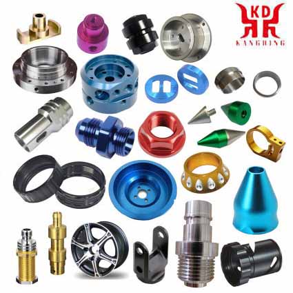
Avec notre réseau de fournisseurs, nous pouvons fabriquer une large gamme de pièces fraisées CNC pour une grande variété d'exigences.
Nous sommes spécialisés dans l'usinage CNC, notre calcul automatique des prix est constamment étendu et couvre actuellement les composants présentant les propriétés suivantes.
Le fraisage consiste principalement à découper la matière qui est usinée avec un outil rotatif à plusieurs arêtes, appelé dents, lèvres ou inserts en carbure, qui exécute des mouvements d'avance programmés de la table de travail dans presque toutes les directions des trois axes possibles sur lesquels peut être déplacée la table sur laquelle est fixée la pièce à usiner.
Avec l’utilisation croissante des fraiseuses à commande numérique, les opérations de fraisage pouvant être réalisées avec ce type de machine augmentent, and thus milling has become a multipurpose machining method. The development of the tools has also contributed to create new possibilities of milling in addition to considerably increasing the productivity, quality and accuracy of the operations carried out.
| Our manufacturing options for CNC milled parts
Component dimensions from 2 mm x 2 mm x 2 mm |
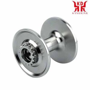
pièces de fraisage CNC
Milling tools
The milling tools are characterized by their outside diameter, the number of teeth, the pitch of the teeth (understood as the distance between two consecutive teeth) and the fastening system of the cutter on the machine.
Types of milling
In the universal milling machines using the appropriate accessories or in the numerical control milling machines the following Planning can be carried out.
The most frequent application of milling is face milling that aims to achieve flat surfaces. For the face milling milling cutters with interchangeable carbide inserts are generally used, there is a very varied range of diameters of these mills and the number of inserts that each milling cutter mounts. Insert manufacturers recommend as a first option the use of round inserts or with 45º angles as an alternative.
Square milling. Square milling is a variant of face milling that consists of leaving perpendicular steps in the part to be machined. For this, square inserts are used that are located in the tool holder in an appropriate way.
Cube Milling. The cubing operation is very common in vertical or horizontal milling machines and consists of preparing the metal dowels or other material such as marble or granite in the appropriate cubic dimensions for subsequent operations. This milling is also done with interchangeable insert face milling cutters.
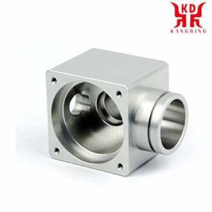
pièces de fraisage cnc Types de fraisage
Cut milling. One of the initial machining operations that must be carried out often consists of cutting the pieces to the determined length starting from commercial bars and profiles of a greater length. Les scies à ruban ou fraiseuses équipées de fraises cylindriques sont utilisées de manière interchangeable pour la découpe industrielle de pièces. Ce qui est important avec les fraises coupantes, c'est qu'elles peuvent être fabriquées en acier rapide ou en métal dur.. Ils se caractérisent par être très minces (sur l'ordre de 3 mm, même si cela peut varier), ayant un grand diamètre et des dents très fines. Un exemple des caractéristiques d'un coupeur serait le suivant: diamètre de 200 mm, épaisseur de 3 mm, diamètre du trou de 32 mm et 128 dents: Bien 128, Grossier 64.
Fraisage de rainures droites. Pour fraiser des rainures droites, des fraises cylindriques avec la largeur de la rainure sont généralement utilisées et souvent, pour augmenter la production, plusieurs fraises sont montées sur l'arbre de fraise permettant d'augmenter la productivité d'usinage. The assembly of several cylindrical strawberries is called a train of strawberries or compound strawberries. Cylindrical burs are characterized by having three cutting edges: the front and the two sides. High speed steel burs are used in most applications since carbide burs are very expensive and are therefore only used in very large productions.
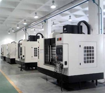
pièces de fraisage cnc Types de fraisage
Shape grooving.. Burs of the appropriate shape for the groove are used, which can be T-shaped, dovetail, etc..
Keyway grooving. Cylindrical strawberries with handles, known in slang as ballerinas, are used that can cut both in a direction perpendicular to its axis and parallel to it.
Milling in Copying. Round insert profile cutters are used for copy milling in order to be able to carry out machining operations in orographies and profiles of changing faces. There are two types of copy cutters: those with a half ball profile and those with a round or toric edge.
Cavity milling. In this type of operation, it is advisable to carry out a prior drilling and from there and with suitable milling cutters, approach the cavity machining, bearing in mind that the radii of the cavity must be at least 15% greater than the radius of the milling cutter.
Lathe-milling. This type of machining uses circular interpolation in numerical control milling machines and is used for both precision hole turning and external turning. The process combines the rotation of the workpiece and the milling tool, making it possible to achieve a cylindrical surface. This surface can be concentric with respect to the center line of rotation of the part, or it can be eccentric if the milling is moved up or down. With axial displacement it is possible to achieve the required length.
Thread milling. Thread milling requires a milling machine capable of simultaneous helical interpolation in two degrees of freedom: the rotation of the part with respect to the axis of the helix of the thread and the translation of the part in the direction of said axis.
Face milling. It consists of milling that is carried out with cylindrical helical burs that attack the milling operation frontally. More and more fully integral carbide burs are used in numerical control milling machines that allow working at very high speeds.
Gear milling. Gear milling is hardly carried out on universal milling machines using the dividing plate anymore, but is done on special machines called gear hobbing machines and with the use of special milling cutters of the appropriate tooth module.
Drilling, reaming and boring. These operations are usually carried out on numerical control milling machines equipped with a tool magazine and using the appropriate tools for each case.
Mortising. It consists of machining keyways in the holes, for which broaching machines are used or a special accessory that is attached to the universal milling machine head and transforms the rotation movement into an alternative vertical movement.
Ramp milling. It is a common type of milling in the machining of molds that is done either with copier milling machines or with numerical control milling cutters.
Comment fonctionne la fraiseuse CNC?
L'introduction de la commande numérique informatisée (CNC) a élargi de manière exponentielle les applications des machines industrielles grâce à l'automatisation programmable de la production et à la réalisation de mouvements impossibles à réaliser manuellement, comme les cercles, lignes diagonales et autres figures plus compliquées qui permettent la fabrication de pièces aux profils très complexes. Cela se traduit également par l'optimisation de nombreuses variables essentielles de tout processus de fabrication.: productivité, précision, sécurité, vitesse, répétabilité, flexibilité et réduction des déchets.
La multiplicité des fraiseuses qui existent aujourd'hui s'est confortablement étendue à la prolifération de leurs homologues équipées de CNC.. En fait, il existe également des kits spéciaux pour transformer d'anciennes fraiseuses en fraiseuse CNC.
Essentiellement, the CNC milling machines are very similar to the conventional ones and have the same moving parts, c'est, the table, the cutting head, the spindle and the side and cross slide carriages. Cependant, they do not have levers or cranks to operate these moving parts, but rather a screen inserted in a panel full of controls and a metal box that houses the electrical and electronic components that regulate the operation of motors destined to carry out the same work that they did. the levers and cranks of the old machines. Among these components is the CNC, which is a computer mainly responsible for the movements of the milling machine through the corresponding software. The combination of electronics and drive motors or servo motors is capable of achieving all possible milling operations.
To understand the movement control exercised by the CNC, we are going to briefly review how a conventional milling machine works.
The figure schematizes a typical milling machine. In this type of machine, the cranks actuate the moving parts manually so that the cutting tool (milling cutter) moves linearly in at least three axes, which are called main axes:
X axis: horizontal and parallel to the clamping surface of the part. It is associated with the movement in the longitudinal horizontal plane of the milling table.
Y axis: forms a direct direction trihedron with the X and Z axes. It is associated with the movement in the horizontal transverse plane of the milling table.
Z axis: where the cutter is mounted, it is the one that has the cutting power and can adopt different positions according to the possibilities of the head. It is associated with the vertical displacement of the machine head.
If the milling machine has a fixed table, these three movements are executed by the spindle.
Cependant, it is clear that the milling of more complex parts will require a greater number of axes whose trajectory is not only linear, but also rotary. At this point is where the concept of CNC comes into play, giving rise to a multiplicity of complementary axes controlled independently and determined by the movement of rotary tables and / or adjustable heads. This gives rise to a variety of machine models that allow the machining of the part by different planes and approach angles.
In the following figure we see an example of a CNC milling machine with its basic components and main (X, Oui, Z) and complementary (B, W) axes.
1 – Column
2 – Workpiece
3 – Milling table, with movement in the X and Y axes
4 – Tournant
5 – Cutting head including spindle motor
6 – CNC control panel
7 – Coolant hoses
X, Oui, Z – Main axes of travel
B – Complementary axis of rotary displacement of the cutting head
W – Complementary axis of longitudinal displacement of the cutting head
pièces de fraisage cnc Types de fraisage
The main function of the CNC is to control the movements of the table, the transverse and longitudinal carriages and / or the spindle along their respective axes by means of numerical data. Cependant, this is not all, because the control of these movements to achieve the desired final result requires the perfect adjustment and the correct synchronization between different devices and systems that are part of every CNC process. These include the main and complementary axes, the transmission system, the workpiece clamping systems and the tool changers, each of which presents its modalities and variables that must also be properly stipulated.
This rigorous control is carried out by software that is supplied with the milling machine and is based on one of the CNC numerical programming languages, such as ISO, HEIDENHAIN, Fagor, Fanuc, SINUMERIK and Siemens. This software contains numbers, letters and other symbols – Par exemple, the G and M codes – that are encoded in an appropriate format to define an instruction program capable of carrying out a specific task. G codes are machine motion functions (rapid moves, feeds, radial feeds, pauses, cycles), while M codes are miscellaneous functions that are required for machining parts, but are not machine motion. (spindle start and stop, changement d'outil, coolant, program stop, etc.). From this it follows that to operate and program this type of machine requires basic knowledge in machining operations on conventional equipment, elementary knowledge of mathematics, technical drawing and handling of measuring instruments.
Actuellement, the use of CAD (conception assistée par ordinateur) and CAM (computer-aided manufacturing) programs is an almost obligatory complement to any CNC machine, which is why, en général, the manufacture of a part involves the combination of three types of software:
GOUJAT: makes the design of the part.
CAM: calculates the displacements of the axes for the machining of the part and adds the feed rates, rotation speeds and different cutting tools.
Control software (included with the machine): receives the instructions from the CAM and executes the orders to move the moving parts of the milling machine in accordance with these instructions.
The following video illustrates the manufacture of a part using CAD / CAM:
CNC milling machines are specially adapted for milling profiles, cavities, surface contours and die cutting operations, in which two or three axes of the milling table must be controlled simultaneously. Although, depending on the complexity of the machine and the programming carried out, CNC milling machines can operate automatically, an operator is usually required to change the cutters, as well as to mount and dismount the workpieces.
Industries that routinely use CNC milling machines include automotive (design of engine blocks, moules, and miscellaneous components), aérospatial (aircraft turbines), and electronics (mold and prototyping), as well as manufacturing of machinery, instruments and electrical components.
 English
 العربية
 中文(漢字)
 Čeština
 Dansk
Dansk Nederlands
 Suomi
Suomi Français
 Deutsch
 Italiano
 日本語
日本語 ಕನ್ನಡ
ಕನ್ನಡ 한국어
한국어 Português
 Русский
 Slovenčina
 Español
 Svenska
 Türkçe

