 English
 العربية
 中文(漢字)
 Čeština
 Dansk
Dansk Nederlands
 Suomi
Suomi Français
 Deutsch
 Italiano
 日本語
日本語 ಕನ್ನಡ
ಕನ್ನಡ 한국어
한국어 Português
 Русский
 Slovenčina
 Español
 Svenska
 Türkçe
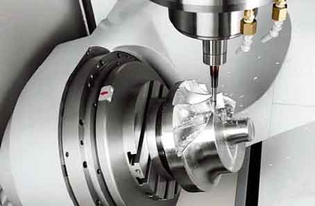
Turbine impellers with complex shapes need to be machined with a 5-axis milling machine to be able to machine every corner of its geometry.
In a modern design system, the geometry that needs to be processed is designed by the CAD system, and then converted into the tool trajectory in the CAM system. The output result is converted into the movement of each of the 5 axes of the milling machine through a post-processing program. For turbomachinery impellers, it is necessary to consider dedicated CAM software. In terms of technology, impeller processing is mainly composed of the following 5 distinct operations:
1, the flow path between the rough machining blades
2, milling the hub part
3. Milling round inlet and outlet edges
4. Finishing the surface of the impeller blade with a small amount of cutting
5. Variable radius fillet processing of the root of the impeller blade
5 fraisage de l'axe de la roue de la turbine
Special attention should be paid to areas on the surface of the impeller blades that cannot be reached by the tool. Because at this time it is easy to cause interference between the cutter and the adjacent blades.
Avant d'adopter les centres d'usinage CNC 5 axes, la plupart des fabricants de turbomachines utilisaient des machines-outils à 3 ou 4 axes pour traiter les roues, et la plupart d'entre eux utilisaient l'usinage par points. C'est, chaque point de la surface de la lame est transformé en un point par la pointe de l'outil. Lorsque l'outil se déplace le long de la surface de la lame, cela laissera des piqûres ou des coins pointus résiduels, et la hauteur de ces creux ou angles vifs dépend des compétences en programmation. Le traitement des points est également une méthode réalisable, mais cette méthode présente des inconvénients inévitables:
1. The surface of the impeller blade is not smooth, leaving some small grooves. These small grooves must be parallel to the flow direction (voir la figure 1).
2. For blades with severe curvatures, due to the close spatial distance of the impeller blades, it is difficult to avoid interference with adjacent blades during processing.
3. If you want to reduce the influence of the groove on the flow field, a long processing time is required. Autrement dit, the tool must move many times around the impeller blades.