 English
 العربية
 中文(漢字)
 Čeština
 Dansk
Dansk Nederlands
 Suomi
Suomi Français
 Deutsch
 Italiano
 日本語
日本語 ಕನ್ನಡ
ಕನ್ನಡ 한국어
한국어 Português
 Русский
 Slovenčina
 Español
 Svenska
 Türkçe
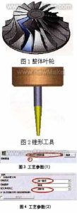
Juoksupyörällä tarkoitetaan liikkuvilla siiveillä varustettua pyörän levyä. Yleisiä juoksupyörien materiaaleja ovat valurauta, pronssi, ruostumaton teräs, mangaanipronssi, Monel, INCONEL, ja ei-metalliset materiaalit, kuten PPS-muovi, fenolihartsi ja niin edelleen. .
Juoksupyörän työstövaatimukset:
5-axis milling impeller shape
(1) Can give a larger energy head;
(2) The loss of gas flowing through the impeller should be small, tuo on, the efficiency of gas flowing through the impeller should be high;
(3) The parameters are appropriate when the gas flows out of the impeller, so that the flow loss when the gas flows through the subsequent fixed components is small;
(4) The impeller type can widen the stable working condition area and high efficiency area of the performance curve of the whole machine. Siksi, the milling of the impeller must adopt 5-axis linkage machine technology.
Step 1: Milling the blade profile
The blade profile milling uses a tapered ring cutter (diameter 3mm, cutting edge length 30mm). See Figure 2. The solution adopted for machining a certain impeller with a single blade type-profile milling between 2 curves, and the milling range of the tool is controlled between the two curves. The choice of cutting type “depends on the amount of milling”, the cutting amount is controlled by the cutting amount to generate the cutting path, kuten kuvassa näkyy 3.
The milling mode is “single path”, and the type of unidirectional addition is defined as “climb milling”. The above two parameters can be defined according to the process requirements, and the specific shape of the impeller should also be considered, kuten kuvassa näkyy
Generate impeller blade surface code
1. Define the geometry
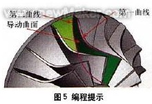
Select the outer edge of the impeller blade as the “first” curve, select the inner edge of the impeller blade as the “second” curve, and select the curved surface between the two blades as the “guide surface”. The above 3 items are required options and are the basic requirements for generating “code”.
The “first” curve restricts the curved surface processing trajectory with the contour of the space, so that the trajectory is processed in the restricted area 1;
The “second” curve restricts the curved surface processing trajectory with the contour of the space, so that the trajectory is processed in the restricted area 2;
“Guiding surface” defines the surface object to be processed on the product, kuten kuvassa näkyy 5.
Set tool axis vector control
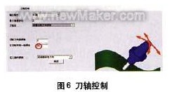
2. Define tool axis control
The method of tool axis tilt is defined as “tilt according to the milling direction”. Considering the need to use the side edge of the tool for processing, it is necessary to control the tool axis vector reasonably at this time. Using the method of tilting according to the milling direction, the tool generates a tool path along the natural direction of the curved surface shape, and the parts processed by such a tool path are smoother. The “side inclination angle in the milling direction” is set to 85°, which mainly takes into account the taper angle of the cutting tool (using the side edge of the milling cutter to process the curved surface of the space can greatly improve the finishing efficiency of the curved surface). See Figure 6.
Pay attention to the above value of 85°, which will make the machine tool rotate continuously. Observe the machine simulation. The rotation mentioned here is due to interference checking. When we use 80° or 85°, observe the tool change and the change of the machine in the machine simulation, and compare them. The tool taper angle is changed to 2.5°, and the settings are reset to compare the differences.
Interference inspection of milling impeller
3. Define interference check
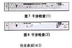
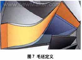
Define the first interference check option: Select the leading surface as the interference check surface, and the system will automatically add the added surface as the interference check surface. The application of this situation is mainly to solve the phenomenon that the twisted guide surface interferes with the tool after being processed, kuten kuvassa näkyy 7.
Define the second interference check option: Select the curved surface between the two impeller blades again as the second interference check surface. When the tool interferes, it will “retract along the direction of the tool axis”. The check surface refers to the interference surface of the tool when used for space curved surface processing, kuten kuvassa näkyy 8.
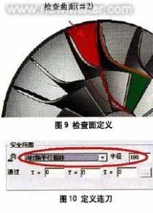
Continuous tool path for machining impeller blades
4. Define continuous tool path
Define the continuous tool path type as “cylinder parallel to Z axis” within the safety range. Since it passes through the X0, Y0, and ZO points and is parallel to the Z axis, the transition between the tool paths will be connected with a cylinder with a radius of 100mm, the axis passing through the 0 point and parallel to the 7 akseli. See Figure 10. Select “Use feed path macro command” in the first feed. In the last retraction point, select “Use retraction path macro”, enter the macro program type as “arc tangent”, and set the arc sweep to 45°. Through the above settings, you can further control the in and out of the tool path, kuten kuvassa näkyy 11-14.
Tool feed path for roughing + viimeistely
The forward and backward tool paths have the same macro command settings, so the same results (the same for each layer) must be produced in the blade processing tool path, kuten kuvassa näkyy 15.
Step 2: Processing the middle area of the blades of the two impellers
When milling the middle area of the blades of the two impellers, a ball-end cutter (diameter 3mm) is used, and the curved surface path is “profiling milling between two curved surfaces”, katso kuva 1. The cutting method is “Z-type milling”, and the cutting sequence is “from inside to outside”, kuten kuvassa näkyy 2. The relative curved surfaces of the blades of the two impellers are defined as the “first” curved surface and the “second” curved surface, and the curved surface between the two blades is defined as the “driving curved surface”. See Figure 3.
1. Define tool axis control
The tool axis will “tilt through the curve”, katso kuva 4. The curve approach type is “approach point”, and an “inclined curve” is established between the outer edges of the two blades, kuten kuvassa näkyy 5. The method of establishing the curve is to use the auxiliary surface of the two impellers to establish an edge curve at the top. The curved surface processing trajectory is restricted by the contour of the space, so that the trajectory is processed in the restricted area, and then the trajectory range of the tool is controlled.
2. Define tool path interference check
Select the “cutting edge” of the tool to participate in the interference check, and also check the “guide surface” ja “check surface”, kuten kuvassa näkyy 6. Check that the surfaces are the inner surfaces of the two impeller blades (tuo on, the “first” surface and “second” surface mentioned above). Tietysti, you must select the two surfaces again. When checking the ‘guide surface’ surface.
3. Define continuous tool path
Define the first feed path as “use feed path macro command”, and define the last tool retraction point as “use retract path macro command”, kuten kuvassa näkyy 7. All slices are connected smoothly with the knife path using “mixed splines”, kuten kuvassa näkyy 8. The feed macro program adopts “vertical tangential radius”, and the arc sweep is 10º, kuten kuvassa näkyy 9. The trajectory of the infeed and outfeed generated in this way is similar to a straight line, as shown in Figure l0.
The third step: the control of the tool axis during the finishing process
Defining the space curve is a good way to control the tool axis, it can make the tool path you define is very smooth, and can greatly shorten the calculation time. kuitenkin, the definition of the space curve requires a very rich experience in actual machining, familiarity with CAD instructions and an understanding of the related functions of 5-axis aviation milling. The Cimatron system will automatically calculate the swing direction of the tool to avoid interference and collision.
Select the leading surface as the interference check surface, and define the tool path generation type, and the tolerance is set to 1.6. A margin of 0.1 is reserved here, which is the margin for processing during the final root removal, kuten kuvassa näkyy 1.
In order to avoid the occurrence of improper processing, we make the tool path extend 10mm at the cutting/cutting place, so as to avoid this kind of situation. as shown in picture 2. Set the percentage value of the tool diameter to 10. The result of this procedure is shown in Figure 3.
Step 4: Tool path control based on roughing program on the basis of finishing
On the basis of finishing, we can easily use the blank layer to build the roughing program, first copy the last program. The roughing and milling settings are shown in Figure 4.
In the roughing tool path, the number of layers and spacing are respectively defined and then the number and spacing of the processing tool path are defined. The spacing here is the 3D distance between the two layers, here you can also define the finishing tool path.
Define the guiding surface in the surface path, cancel the original guiding surface, and select the new revolving surface just created. Click the “Advanced” option and select “Generate tool path on the front side”, kuten kuvassa näkyy 5. If this option is not selected, the tool path will be generated in the entire impeller blade. This dialogue pivot can also be used to define the angle between the tool path and the surface.
Kuva 5, the angle setting between the cutting path and the curved surface
Calculate the program segment to get the rough machining + finishing tool path, kuten kuvassa näkyy 6.
Step 5: Add blanks to optimize the rough tool path
Add blanks in each program segment to optimize the cutting path. Establish 3 curved surfaces between the impeller blades, and use these 3 surfaces to define the blank. The blade is shown in Figure 7.
Adjust the transparency of the blade so that it is convenient to observe the blank. When selecting, we can see that a lot of toolpath trajectories will be generated, kuten kuvassa näkyy 8.
In addition to parts, there are many toolpaths that have not participated in cutting. Now through simple settings to cancel the path of these blanks. Copy the last program and edit it, open the “Rough Definition” option, and select the rough surface you just defined, kuten kuvassa näkyy 9. Lopulta, calculate the program to get the tool path trajectory. Kuten kuvasta näkyy 10.
If you see the tool path trajectory connected in space (after the blank is defined), it means that the blank you defined plays a certain role in the tool path calculation. If you are not satisfied with this connection method, you can change the corresponding parameters in “Continuous feed” until you get a satisfactory result.